Flip flop is one of the most important parts of digital electronics. Flip-flops are synchronized memory elements that can store only 1 bit. The output of the flip-flop depends on its inputs as well as its past outputs. Depending on the control inputs used, there are 4 types of flip-flops – SR flip-flop, D flip-flop, JK flip-flop, and T flip-flop.
‘T’ in the name ‘T flip-flop’ stands for ‘Toggle’. In this article, we are going to discuss T flip-flop, its truth table, its circuit, its application, and its advantages and disadvantages.
What is a T flip-flop?
In JK flip-flop, the state J=1, K=1 is known as ‘Toggle state’. Under this condition, the present output becomes the complement of its immediate past output. T flip-flop is only used for this toggle condition. It has only one control input pin – T. Like other flip-flops it also has a clock/enable pin and output pins Q and $\overline{Q}$.
When the enable or clock pin is deactivated, the flip-flop goes to the memory state which means the output or the stored bit does not change even if the control input changes. Now after activating the clock, if the input is T=0 then the present output is the same as its immediate past output i.e., the flip-flop stays in the memory state. But when T=1, the flip-flop goes to toggle state and the present output becomes the complement of its previous output.
Truth Table of T Flip-flop
The truth table of the T flip-flop is given below.
| Input | Output | State | ||
| EN | T | Q(t) | $\overline{Q(t)}$ | |
| 0 | × | Q(t-1) | $\overline{Q(t-1)}$ | Memory |
| 1 | 0 | Q(t-1) | $\overline{Q(t-1)}$ | Memory |
| 1 | 1 | $\overline{Q(t-1)}$ | $\overline{\overline{Q(t-1)}}=Q(t-1)$ | Toggle |
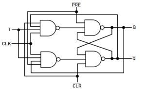
T flip flop with NAND gates
We can build a T flip-flop with NAND gates using the following diagram.
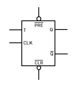
T flip flop symbol
While showing T flip-flop in a circuit diagram it is better to use the following symbol. This is the symbol of a positive level triggered T flip-flop.
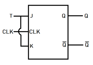
T flip flop using JK flip flop
As mentioned before, there is a toggle mode in the JK flip-flop. The toggle condition for JK flip-flop is J=1 and K=1. We can make a T flip-flop using the JK flip-flop simply by applying the same input to J and K, or by connecting the input pins J and K together. The following diagram describes how to design a T flip-flop using a JK flip-flop.
SR flip-flop and D flip-flop can also be converted into T flip-flop.
T flip flop Applications
T flip-flop is used for toggling. It is used in frequency dividers, counters, binary counters, etc. Below we have explained how a T flip-flop can be used as a frequency divider.
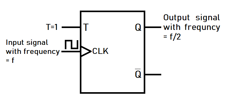
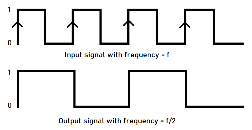
Here a positive edge-triggered T flip-flop has been used. The control input T is kept HIGH i.e. T=1 and the original signal is given to clock or enable pin. Now when a positive edge occurs at the clock input, the flip-flop goes to the Toggle mode, and output changes. After the edge is passed, the flip-flop moves to the memory state. Suppose, now, the output of the flip-flop is 1. Then for the next positive edge, the flip-flop again moves to toggle mode and the output changes to 0. Then for the next positive edge, the output becomes 1 again and this goes on. Thus, for a full cycle of the original signal we get a half cycle at the output i.e., the output signal’s frequency is half of the original signal’s frequency.
T flip flop Advantages and Disadvantages
T flip-flops are easy to use in frequency dividers, counters, etc. But T flip-flop has some disadvantages too. Unlike SR, D, and JK flip-flop, T flip-flop does not have any set or reset state. T flip-flop has some specific applications only. There are also no ICs available for T flip-flops.
Author
Subhrajyoti Choudhury
