A Latch is a basic memory element that operates with signal levels (rather than signal transitions) and stores 1 bit of data. Latches are said to be level sensitive devices. Latches are useful for storing information and for the design of asynchronous sequential circuits.
SR Latch
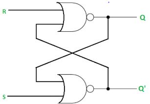
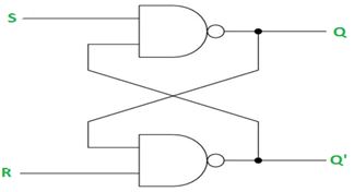
The SR latch is a circuit with two cross-coupled NOR gates or two cross-coupled NAND gates with two inputs labelled S (for Set) and R (for Reset) and with two complementary outputs Q and Q’.
SR latch using NOR gates
The SR latch constructed using two cross-coupled NOR gates is shown in Fig.1. The latch has two useful states. When output Q=1 and Q’= 0, the latch is said to be in the Set state. When Q= 0 and Q’=1, it is in Reset state. Normally, outputs Q and Q’ are complement to each other.

Working of SR NOR latch
Case 1: When S=0 and R=1, then by using the property of NOR gate (if one of the inputs to the gate is 1 then the output is 0), therefore the output Q=0 since R=1 and if Q=0 and S=0 then Q’ becomes 1, hence Q and Q’ are complement to each other. This is the Reset condition as output Q=0 when R=1.
Now if R goes back to 0, the circuit remains in the Reset state i.e in another word if we remove the inputs i.e. S=0 and R= 0, then let if Q’ =1 then again by using the property of NOR gate Q becomes 0, it seems we get the previous output which gets stored in the latch, therefore S=0 and R=0 are called as memory condition.
Case 2: When S=1 and R=0, then by using the property of NOR gate, we get Q’ =0 and now if R=0 and Q’ =0 then Q becomes 1 which is the condition for the Set state. Similarly, if S goes back to 0, then the circuit will remain in the set state, i.e. S=0 and R=0 is the memory or hold state which means latch is holding or storing the previous output.
Case 3: When S=1 and R= 1, then both the outputs Q and Q’ becomes 0 by using the property of NOR gate, which violates the requirement that both the outputs must be complement of each other. In normal operation, this condition is avoided by making sure that 1’s are not applied to both the inputs simultaneously.
The truth table of SR NOR latch is given below
| S | R | Q | Q’ |
| 0 | 0 | Memory/hold state | |
| 0 | 1 | 0 | 1 |
| 1 | 0 | 1 | 0 |
| 1 | 1 | Invalid state (not used) | |
SR latch using NAND gates
The SR latch using two cross-coupled NAND gates is shown in Fig.2.

Working of SR NAND latch
Case 1: When S=0 and R=1 then by using the property of NAND gate (if one of the inputs to the gate is 0 then the output is 1), therefore Q becomes 1 as S=0, putting the latch in the Set state and now since Q= 1 and R=1 then Q’ becomes 0, hence Q and Q’ are complement to each other. Now when the S input goes back to 1, the circuit remains in the set state, which means when S=1 and R= 1, the latch is in memory state i.e. holding the previous output.
Case 2: When S=1 and R=0 then Q’ becomes 1 and since Q’=1 and S=1 then Q goes to 0, putting the latch in the Reset state and both the outputs Q and Q’ are complement to each other. Similarly, when the R input goes back to 1, the circuit remains in the reset state, which simply means when S=1 and R=1 the latch is in-memory state.
Case 3: When both the inputs S and R are 0 then by using the property of NAND gate we get both the outputs Q and Q’ equals to 1, which violates our assumption of complementary outputs, hence this condition is not used when operating with NAND SR latch.
The truth table of SR NAND latch is given below
| S | R | Q | Q’ |
| 0 | 0 | Invalid condition (not used) | |
| 0 | 1 | 1 | 0 |
| 1 | 0 | 0 | 1 |
| 1 | 1 | Memory/ hold state | |
Author:
Shivani Gupta
Institute of Engineering and Technology
Lucknow, U.P.

Great explanation of latches! The breakdown of the SR latch and the truth table really helped clarify how they function in digital circuits. Thanks for sharing such detailed insights!
Great explanation of SR Latches! I appreciate the clarity of the truth table and how you broke down the functioning of latches. It’s really helpful for someone trying to grasp the basics of digital electronics. Looking forward to more posts like this!
This post really clarified the concept of latches for me! The explanation of the SR Latch and its truth table was especially helpful. I appreciate the clear examples, which made it easier to understand how they work in digital circuits. Looking forward to more informative posts like this!
Great explanation of SR latches! The truth table makes it so much clearer how these circuits operate. I found the examples really helpful for understanding the practical applications. Keep up the good work!
Thanks for the clear explanation of latches and their functionality! The SR latch details and the truth table really helped me understand how they operate. Looking forward to more posts like this!
I really appreciated the clear explanation of latches in this post! The breakdown of the SR latch and the truth table was super helpful for me to understand how they function in digital circuits. Looking forward to more posts like this!