An Adder is a digital logic circuit in electronics that performs the operation of additions of two number. Adders are classified into two types: half adder and full adder. The half adder (HA) circuit has two inputs: A and B, which add two input binary digits and generate two binary outputs i.e. carry and sum.
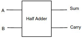
Let’s see an addition of single bits.
0+0 = 0
0+1 = 1
1+0 = 1
1+1 = 10
These are the least possible single-bit combinations. But the result for 1+1 is 10, the sum result must be re-written as a 2-bit output. Thus, the equations can be written as
0+0 = 00
0+1 = 01
1+0 = 01
1+1 = 10
The bold digit is the sum output. The output ‘1’of ‘10’ is carry output. ‘SUM’ is the normal output and ‘CARRY’ is the carry output.
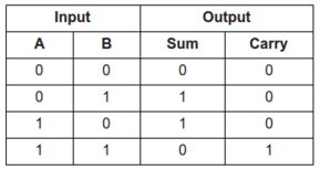
Truth table of half adder
The truth table of the Half Adder Circuit is shown in figure 2.
Implementation of half adder
Logical expression for Sum,
![]()
Logical expression for Carry,
Carry = AB
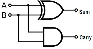
The HA works by combining the operations of basic logic gates, with the simplest form using only an XOR and an AND gate.
Note:
1. Minimum number of NAND Gate required implementing HA = 5
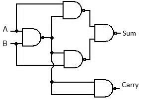
2. Minimum number of NOR Gate required implementing HA = 5
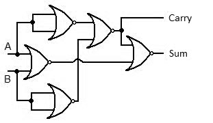
3. Number of Multiplexers required implementing HA = 3
4. HA can be implemented by a combination of one 2×4 decoder and one OR gate.
