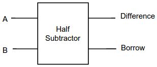
A subtractor is a digital logic circuit in electronics that performs the operation of subtraction of two number. Subtractors are classified into two types: half subtractor and full subtractor. The half subtractor (HS) circuit has two inputs: A and B, which subtract two input binary digits and generate two binary outputs i.e. borrow and difference.

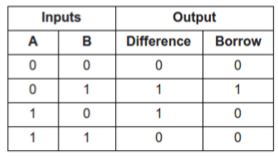
Truth table of half subtractor
The truth table of the HS Circuit is shown in figure 2.

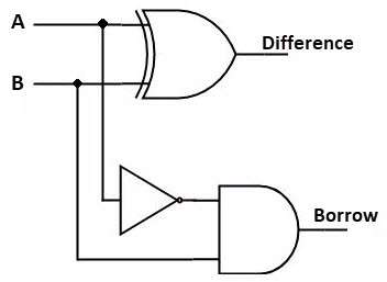
Implementation of HS
Logical expression for difference,
![]()
Logical expression for borrow,
![]()

The HS works by combining the operations of basic logic gates, with the simplest form using only an XOR, one NOT and an AND gate.
Note:
1. Minimum number of NAND Gate required implementing HS = 5
2. Minimum number of NOR Gate required implementing HS = 5
3. Number of Multiplexers required implementing HS = 3 (2×1 Multiplexer)
4. HS can be implemented by a combination of one 2×4 decoder and one OR gate.
