In digital electronics, we classify circuits into two primary types which are – combinational circuits and sequential circuits. In the case of combinational circuits, the output depends only on the present input. Whereas, in the case of the sequential circuits, the output depends on the present input as well as the past output(s)/input(s). Due to this dependency on past outputs, the sequential circuits require a memory. This is important to understand this article better. Latch and flip-flop are both memory elements or circuits. Both of them can store only 1 bit – either logic-1 or logic-0. In this article, we will discuss the difference between latch and flip flop, and give a brief description of them.
Difference between Latch and Flip flop in tabular form
In the following table, we are going to discuss the differences between latch and flip flop in detail.
| Latch | Flip flop |
| Latch is the most basic memory element | Flip-flop is made using latches |
| Latch is the simplest memory element | Flip-flop is more complex in nature |
| Latch does not have any enable input | Flip-flop has Enable input commonly which is driven by a periodic clock signal. |
| Latch is asynchronous in nature | Flip-flop is synchronous in nature |
| Latch usually does not have any overriding inputs. | All the practical and commercially available flip-flops have PRESET and CLEAR input pins. |
| Latch requires a smaller number of logic gates | Flip-flop requires a greater number of logic gates. |
| Latches do not have any solo practical applications other than in flip-flops. | Flip-flop is made using latches and has solo practical applications. |
What is Latch?
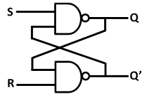
A latch is the simplest and most basic memory element. It is made using logic gates and it can store only 1 bit – either Logic-0 or Logic-1. It will be easier to understand latches if we discuss the working of it. So, let’s discuss the working of the most basic latch – SR or Set-Reset latch.
SR latch has two inputs and two outputs. It got its name from its two input pins which are Set and Reset. The output pins of the SR latch are termed as Q and Q’ (or Q bar). The output pins are named as such because their values are always complemented of each other. There are two types of SR latches – active-high input SR latch and active-low input SR latch. Let’s discuss them one-by-one in details.
In the case of the active-high input SR latch, there are 4 modes of operation, which are:
1. The output Q is set to HIGH or logic-1 when Set input is HIGH (S=1) and Reset input is LOW (R=0). This is called Set State.
2. The output Q is set to LOW or logic-0 when Set input is LOW (S=0) and Reset input is HIGH (R=1). This is called Reset State.
3. When S=0 and R=0 the output Q does not change i.e., the present output is equal to the past output [Qn = Qn-1]. This is called Steady State, Memory State or No-Change State.
4. When S=1 and R=1, the output Q and Q’ becomes unpredictable. In this case, the outputs become dependent upon the delay of the gates. This state is called Forbidden State.
The truth table and circuit diagram of the active-high input SR latch are given below.
| S | R | Qn | $\overline{Q_{n}}$ | State |
| 0 | 0 | Qn-1 | $\overline{Q}_{n-1}$ | Memory |
| 0 | 1 | 0 | 1 | Reset |
| 1 | 0 | 1 | 0 | Set |
| 1 | 1 | — | — | Forbidden |

Now, the active-low input SR latch also has 4 modes of operation. But the difference between active-high input and active-low input SR latch is that in the case of active-low input SR latch:
- Set State: S=0, R=1
- Reset State: S=1, R=0
- Memory State: S=1, R=1
- Forbidden State: S=0, R=0
The truth table and the circuit diagram of the active-low input SR latch are given below.
| S | R | Qn | $\overline{Q_{n}}$ | State |
| 0 | 0 | — | — | Forbidden |
| 0 | 1 | 1 | 0 | Set |
| 1 | 0 | 0 | 1 | Reset |
| 1 | 1 | Qn-1 | $\overline{Q}_{n-1}$ | Memory |

Disadvantages of Latches
Though latch is the simplest memory element, it has many disadvantages like
1. Asynchronous: Latch is asynchronous in nature so it is less immune to glitches.
2. Input/output ratio: To store 1 bit in latch we need two inputs (set and reset)
3. Forbidden state: One of the states is not used i.e., we waste a state of operation.
What is Flip Flop?
Flip-flop is a synchronous memory element that is used to store 1 bit – either logic-0 or logic-1. Flip-flops can be classified in two ways. Based on the type of control inputs flip-flops can be classified into 4 categories i.e.
- SR Flip-flop
- D Flip-flop
- JK Flip-flop
- T Flip-flop
Based on the clocking mechanism flip-flops can be classified into the following categories i.e.
- Master-Slave Flip-flop
- Pulse triggered Flip-flop
- Edge triggered Flip-flop
- Data Lock Out Flip-flop
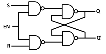
The main difference between latch and flip flop is that flip-flops have an enable input for which they need additional circuitry called “steering circuit” along with a latch circuit. Due to this steering circuit, flip-flops are more immune to glitches. So, one of the disadvantages of latches is removed here. Let’s see how the enable input works in SR flip-flop which is made using active-low input SR latch using the following table.
| EN | S | R | $\overline{Q}$ | $\overline{R}$ | Qn | $\overline{Q_{n}}$ | State |
| 0 | x | x | 1 | 1 | Qn-1 | $\overline{Q}_{n-1}$ | Memory |
| 1 | 0 | 0 | 1 | 1 | Qn-1 | $\overline{Q}_{n-1}$ | Memory |
| 1 | 0 | 1 | 1 | 0 | 0 | 1 | Reset |
| 1 | 1 | 0 | 0 | 1 | 1 | 0 | Set |
| 1 | 1 | 1 | 0 | 0 | — | — | Forbidden |

The requirement of two inputs to store 1 bit can be removed using D flip-flop as it requires only 1 input pin to store 1 bit. But again, we also lose two states or modes of operation. JK flip-flop does not have any forbidden state but instead, we face toggling or oscillatory output. Toggle or T-flip-flop is derived from JK flip-flop and has only 1 input pin. The truth table of D flip-flop and JK flip-flop is given below.
| EN | D | Qn | $\overline{Q_{n}}$ | State |
| 0 | x | Qn-1 | $\overline{Q}_{n-1}$ | Memory |
| 1 | 0 | 0 | 1 | Reset |
| 1 | 1 | 1 | 0 | Set |
| EN | J | K | Qn | $\overline{Q_{n}}$ | State |
| 0 | x | x | Qn-1 | $\overline{Q}_{n-1}$ | Memory |
| 1 | 0 | 0 | Qn-1 | $\overline{Q}_{n-1}$ | Memory |
| 1 | 0 | 1 | 0 | 1 | Reset |
| 1 | 1 | 0 | 1 | 0 | Set |
| 1 | 1 | 1 | (Qn-1) | ($\overline{Q}_{n-1}$)’ | Toggle |
MS or Master-Slave flip-flop was an early attempt to remove toggling from JK flip flop. It used pulse-triggered flip-flops so the error due to glitches was still there. Data lock out flip-flips used edge-triggered master and pulse-triggered slave. So, it was more immune to glitches.
Conclusion
Flip-flops can be termed as synchronized latches. The disadvantages we find in latches are removed in flip-flops as discussed above.
Author
Subhrajyoti Choudhury
