Flip-flops are synchronized sequential circuits. They are used as a memory that can store either logic-1 or logic-0. Flip-flop is more reliable than latch as it has a clock or an enable pin that controls the output state. If enable pin is not active, it does not let the output state change even if the state of the inputs changes. Depending on the type of control inputs used to set or reset the flip-flop, flip-flops are of four types –
- SR flip-flop
- D flip-flop
- JK flip-flop
- T flip-flop
In this article, we will discuss the D flip-flop, its circuit diagram, truth table, and its applications.
What is D flip flop?
SR flip-flop, the most basic flip-flop in terms of design, has some flaws such as it has a “not used” state and it requires 2 input lines to store 1 bit. To overcome these flaws a flip-flop had been developed, called as D flip-flop. The D stands for ‘data’. A D flip-flop requires only one control input, and an enable or clock pin to store one bit. D flip-flop also does not have any “not used” state.
D flip flop Truth Table
When the enable input is deactivated the flip-flop goes to memory state i.e. the stored value does not change even if the input (D) changes. The enable input is activated the output is HIGH if D is HIGH and output is LOW if D is LOW. The truth table of a D flip-flop is given below.
| Input | Output | State | ||
| EN | D | Q(t) | $\overline{Q(t)}$ | |
| 0 | × | Q(t-1) | $\overline{Q(t-1)}$ | Memory |
| 1 | 0 | 0 | 1 | Reset |
| 1 | 1 | 1 | 0 | Set |
D flip flop using NAND gate
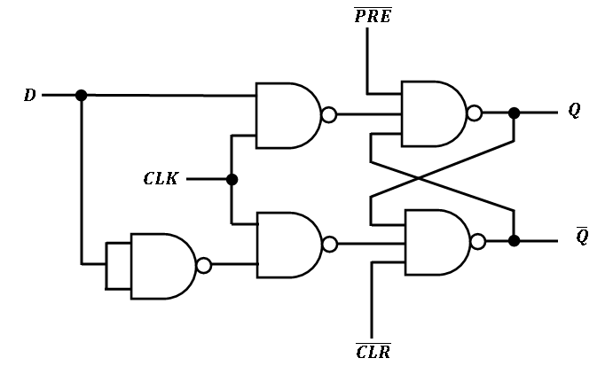
A D flip-flop has one control input pin (data pin), an enable/clock pin, output pins Q and $\overline{Q}$, and like other practical flip-flops, it also has preset and clear inputs. A D flip-flop can be made using five NAND gates. The circuit diagram of D flip-flop using NAND gate is given below.
D flip flop symbol
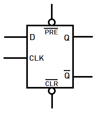
While introducing D flip-flop in a circuit diagram it is better to use the following symbol.
D flip flop using SR flip flop
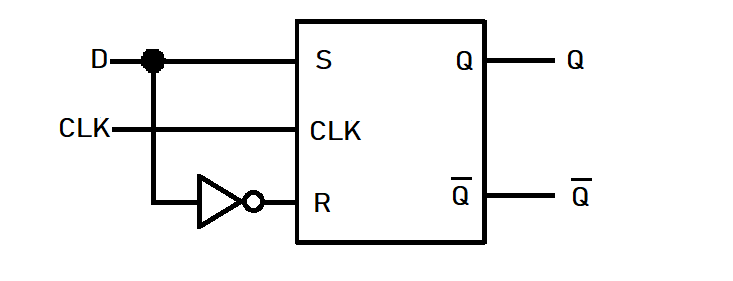
SR flip-flop can be easily transformed into a D flip-flop by connecting S and R input pins with a NOT gate. The input pin of the not gate is connected to S and output pin is connected to R. The block diagram below describes how a SR flip-flop can be converted into a D flip-flop.
Applications of D flip flop
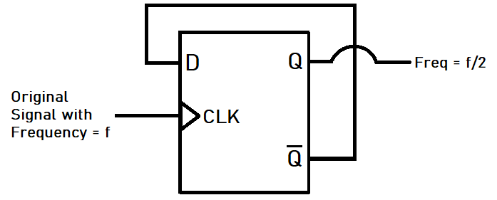
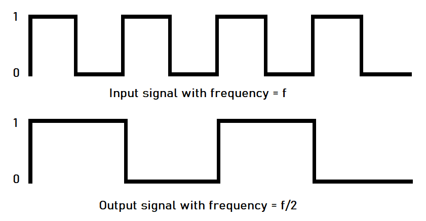
D flip-flop is used for many purposes such as delay, data synchronizer, frequency divider, in shift registers. Below we have described how D flip-flop can be used as a frequency divider. Here the output $\overline{Q}$ is connected to the input pin D and the signal with the original frequency f is connected to CLK. We have used a positive edge-triggered D flip-flop here.
Conclusion
D flip flop is able to overcome the flaws of an SR flip-flop partially. It also has many applications. We can improve the functionality of D flip-flop by connecting an SR flip-flop to its output to make it a master-slave D flip-flop. There are some D flip-flop ICs available in the market. The numbers of these ICs are – 74LS74 74LS175, 74LS273, 4013B, etc.
