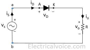
In this article, we will see the analysis of Single Phase Half Wave Uncontrolled Rectifier with Resistive (R) Load as shown in Figure 1. Vs is supply and ‘is‘ is the source current. VD and ‘iD‘ is the diode voltage and current respectively. Vo and ‘io‘ is the load voltage and current respectively.
Vs = Vmsin(ωt)
Step-1: Write KVL in the given circuit
vs − vD − vo = 0
vab = vs = vD + vo
vab = vs = Vmsin(ωt)
vba = − vab = − Vmsin(ωt)
Step-2: Device working status
In the positive half cycle, the diode is forward biased and is turned ON at ωt = 0°.
At ωt = π, the current through the diode falls to zero i.e. below zero and simultaneously a reverse voltage appears across the diode and it turns OFF.
1). 0 < ωt < π
Diode is forward biased. Hence turns ON
vD = 0 V
vo = vab = Vmsin(ωt)
io = is = iD = (vo)/R = (Vmsin(ωt))/R
2). π < ωt < 2π
Diode is reversed biased. Hence turns OFF
io = is = iD = 0 A
vo = 0 V
vD = vab = Vmsin(ωt)
3). 2π < ωt < 3π
Diode is forward biased. Hence turns ON
vD = 0 V
vo = vab = Vmsin(ωt)
io = is = iD = (vo)/R = (Vmsin(ωt))/R
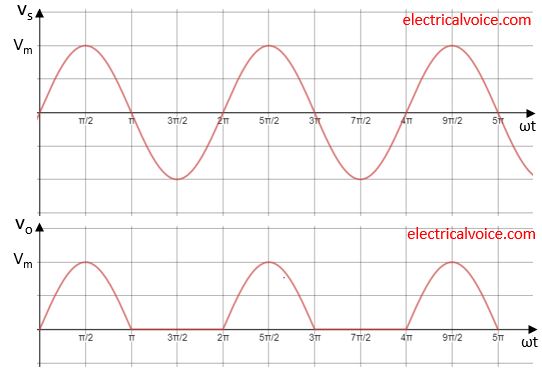
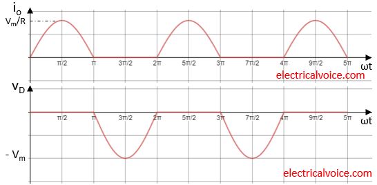
The waveforms for load voltage(vo), and current(io), diode voltage(vD) is shown in figure 2. The waveforms of supply current and diode current is same as load current.
Note: For a resistive load, vo and io waveform will be same in nature except in magnitude.
Step-3:
1). Diode starts conducting at ωt = 0°
2). Extinction angle (β) = π
3). Conduction angle (γ) = β − 0 = π − 0 = π
4). Conduction time (tc) = γ/ω = π /ω
5). Diode reverse biased time = (2π − π)/ω = π/ω
6). Peak Inverse voltage (PIV) = Vm
Step-4:
Average Values
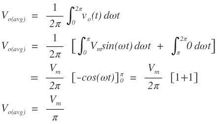
The average output voltage Vo(avg) across load R is given by
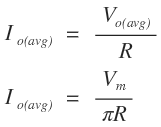
The average output current Io(avg) through the load R is given by
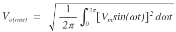
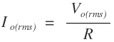
RMS values