Statement
Blondel’s theorem states that if a network is supplied through P conductors, the total power is measured by adding the readings of P wattmeters so arranged that a current element of a wattmeter is in each line and the corresponding voltage element is connected between that line and a common point.
Note: If the common point is located on one of the lines, then the total power may be measured by P−1 wattmeters.
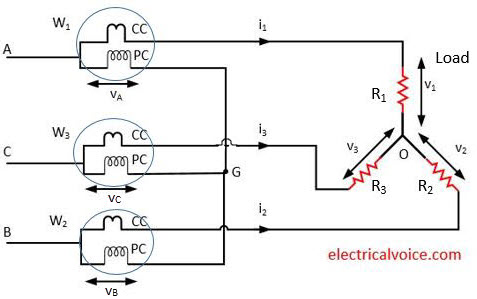
Let us take a simple example of a 3-phase 3 wire system for power measurement. The diagram for such system is shown in figure 1.

The current coils (CC) of wattmeters (W1, W2, W3) are connected to respective line conductors. The potential coils (PC) are connected to common point G. Star load is connected to the system.
v = potential of point G w.r.t. neutral point O.
Instantaneous power consumed by the load = v1i1 + v2i2 + v3i3 ………………..(1)
Now
Reading of wattmeter W1 , t1= vAi1
Reading of wattmeter W2 , t2 = vBi2
Reading of wattmeter W3 , t3 = vCi3
Since
v1 = v + vA
v2 = v + vB
v3 = v + vC
Therefore,
t1= (v1 − v)i1
t2 = (v2 − v)i2
t3 = (v3 − v)i3
Sum of 3 wattmeter readings = t1 + t2 + t3
= (v1 − v)i1 + (v2 − v)i2 + (v3 − v)i3
= v1i1 + v2i2 + v3i3 − v(i1 + i2 + i3)
Apply KCL at node O,
i1 + i2 + i3 = 0
Therefore,
Sum of wattmeter readings = v1i1 + v2i2 + v3i3 ……………(2)
Since equation (1) and (2) are equal. Hence the total instantaneous power measured by the three wattmeters is equal to the total power consumed in the load.

The whole point of Blondel’s theorem is that you can use P-1 wattmeters! This example demonstrates that you can use P wattmeters.
Can anybody point me to the proof of Blondel’s Theorem?
Regards
Suppose you think about delta connection where there is no neutral point . There use of 3 watt meter is useless because we would have taken one phase as reference so one wattmeter would show 0 reading. For ex – If we take b as reference then you will find wattmeter connected to b phase would show 0 as voltage will be 0. So in that case two wattmeter is useful rather than 3 wattmeter .
So to be precise , Blondels theorem states if there is P conductors and neutral line then minimum no of wattmeter required is P but if there is no neutral line present then minimum no of wattmeter required is P-1.
Proofs are “out there” on the Web. The original was in English (Blondel was French), and dealt only with resistive loads. The number of power meters needed is one fewer than the number of wires. I suspect it applies to all linear time-invariant loads, however, and I’m interested in showing that. It relies on taking one wire as a reference for voltage, and (I think) on recognizing that the sum of the currents into any node is zero.
By the way, it seems to me that we use the theorem even for single-phase systems that have just two wires, only we don’t think of it a simple case of Blondel’s theorem.
It is not really a proof but if you think of the center node of the Y, it cannot store power. So, at any instant, power flowing on any pair of lines has to be equal to the power flowing in the third line. In other words, if you know the power flowing in any two of the lines you know the total power.
The diagram is not according to Blondel’s.. Where’s N-1? This is 3-ph, 3-wire remember? Must be 2-element watt-meter with line to line potential. For 3-ph 4-wire, then 3-element (N-1) watt-meter is used
The diagram is in accordance with Blondell. This system has three wires (no neutral wire) so it requires three wattmeters, with the voltmeters connected to a common point. Since the common point in the diagram is not one of the three wires, then 3 wattmeters are required. If you move the common volt meter connection to one of thre 3 wires, then you can eliminate one wattmeter and only 2 are required.
There’s a mistake in the derivation. According to this article, the reading of the wattmeter “W_1”, denoted by “t_1”, is “t_1 = v_A * i_1”. However, that product is an instantaneous power, but wattmeters don’t read that, they read average power, a.k.a. active power. So the wattmeter “W_1″ actually reads avg(v_A * i_1)” where “avg()” means the average of its argument.
The bad thing about the proof given in this article is that it’s valid for wye-connected devices, not for delta-connected devices, and more generally not for three-wire networks.