Construction
The construction of a single phase Electrodynamometer Power Factor Meter is shown in fig. 1. It consists of a fixed coil which acts as the current coil. This coil is split up into two parts and carries the current of the circuit under test. Therefore, the magnetic field produced by this coil is proportional to the main current.
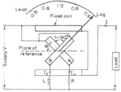
Two identical pressure coils A and B pivoted on a spindle constitute the moving system. Pressure coil A has a non-inductive resistance R connected in series with it, and coil B has a highly inductive choke coil L connected in series with it. The two coils are connected across the voltage of the circuit. The values of R and L are so adjusted that the two coils carry the same value of current at normal frequency, i.e., R = ωL.
The current through coil A is in phase with the circuit voltage while that through coil B lags the voltage by an angle Δ which is nearly equal to 90°. The angle between the planes of coils is also made equal to Δ. There is no controlling device. Connections to moving coils are made through thin silver or gold ligaments which are extremely flexible and thus give a minimum control effect on the moving system.
Working Principle
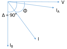
In order to simplify the problem, we assume that the current through coil B lags the voltage by exactly 90°. Also that the angle between planes of coils is exactly 90°, (i.e., Δ = 90°).
Now there will be two deflecting torques, one acting on coil A and the other on coil B. The coil windings are so arranged that the torques due to the two coils are opposite in direction. Therefore the pointer will take up a position where these two torques are equal.
Let us consider the case of a lagging power factor of cos Φ.
Deflecting torque acting on coil A is:
TA = KVI Mmax cos Φ sin θ
where, θ = angular deflection from the plane of reference
Mmax = maximum value of mutual inductance between the two coils.
This torque say act in the clockwise direction.
Deflection torque acting on coil B is:
TB = KVI Mmax cos (90° − Φ) sin (90° + θ) = KVI Mmax sin Φ cos θ
This torque acts in the anticlock wise direction. The value of Mmax is the same in the two expressions, owing to similar constructions of the coils.
The coils will take up such a position that the two torques are equal.
Hence, at equilibrium,
TA =TB
⇒ KVI Mmax cos Φ sin θ = KVI Mmax sin Φ cos θ
⇒ θ = Φ
Therefore the deflection of the instrument is a measure of the phase angle of the circuit. The scale of the instrument can be calibrated indirectly in terms of power factor.
The phasor diagram is also shown for the circuit such that the current in the coil A is approximately at an angle of 90° to the current in the coil B.
Comparison with the moving iron power factor meter
- In Electrodynamometer Power Factor Meter working forces are very small as compared to moving iron type.
- The scale of the moving iron type extends over 360°.
- Electrodynamometer type is more accurate than the moving iron type.
image credit: allsyllabus.com
