Voltage to Current Converter or V-I converter is an electronic circuit that creates a current that is proportional to the applied input voltage. Basically it maintains the load current at a value that is independent of the load impedance variation. In this article, we will see the different op-amp based V-I converter, its working and its applications. Basically three circuits are there for V-I converter.
Floating Load Voltage to Current Converter
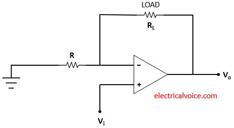
Floating load voltage to current converter circuit as shown in figure 1. The input Vi is applied at the non-inverting terminal. Vo is the output voltage. The resistance R connected to the inverting terminal of the op-amp is grounded. The load resistor (RL) is floating in this V-I converter circuit. It is said to be floating because the load resistance is not connected to the ground.
Analysis
The analysis of the V-I converter circuit is shown in figure 2. Since the op-amp is ideal and negative feedback is present, the voltage of the inverting terminal (V−) is equal to the voltage of the non-inverting terminal (V+ = Vi), according to the virtual short concept.
V− = V+ = Vi
The currents entering both terminals of the op-amp are zero since the op-amp is ideal.
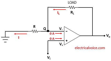
Let current I flows through the resistor R.
\begin{equation} \label{eq:poly}
I=\frac{V_{i}-0}{R}=\frac{V_{i}}{R}
\end{equation}
Apply KCL at node Q
$I_{L} = 0 + I$
\begin{equation} \label{eq:poly}
I = I_{L}
\end{equation}
From equations (1) and (2), we have
\[
\quicklatex{color=”#000000″ size=20}
\boxed{I_L=\frac{V_{i}}{R}}
\]
If input voltage Vi and Resistance (R) is fixed then the load current (IL) is independent of the load resistance (RL).
Ground Load Voltage to Current Converter
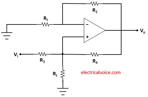
Ground load voltage to current converter circuit as shown in figure 3. The input Vi is applied as shown in figure 3. Vo is the output voltage. The resistance R1 connected to the inverting terminal of the op-amp is grounded. The load resistor (RL) is grounded in this V-I converter circuit. It is said to be grounded because the load resistance is connected to the ground.
Analysis
The analysis of the V-I converter circuit is shown in figure 4. Let the voltage of node Q is V1. Since the op-amp is ideal and negative feedback is present, the voltage of the inverting terminal (V−) is equal to the voltage of the non-inverting terminal (V+ = V1), according to the virtual short concept.
V− = V+ = V1
The currents entering both terminals of the op-amp are zero since the op-amp is ideal.
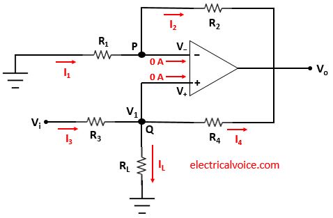
Let current I1 and I2 flows through the resistor R1 and R2 respectively.
\begin{equation} \label{eq:poly}
I_1=\frac{0-V_{1}}{R_1}=-\frac{V_{1}}{R_1}
\end{equation}
\begin{equation} \label{eq:poly}
I_2=\frac{V_{1}-V_{o}}{R_2}
\end{equation}
Apply KCL at node P
$I_{1} = 0 + I_2$
\begin{equation} \label{eq:poly}
I_1 = I_{2}
\end{equation}
From equations (3), (4), and (5), we have
$-\frac{V_{1}}{R_1}=\frac{V_{1}-V_{o}}{R_2}$
Therefore
$V_o=V_1[1+\frac{R_2}{R_1}]$
or we can write it as
\begin{equation} \label{eq:poly}
V_1 =\frac{V_o}{[1+\frac{R_2}{R_1}]}
\end{equation}
The current I3 , I4 and IL flows through the resistor R3 , R4 and RL respectively.
\begin{equation} \label{eq:poly}
I_3=\frac{V_{i}-V_{1}}{R_3}
\end{equation}
\begin{equation} \label{eq:poly}
I_4=\frac{V_{1}-V_{o}}{R_4}
\end{equation}
Apply KCL at node Q
$I_{3} = 0 + I_4 + I_L$
\begin{equation} \label{eq:poly}
I_3 = I_{L}+I_4
\end{equation}
From equations (7), (8), and (9), we have
$\Rightarrow \frac{V_{i}-V_{1}}{R_3}=I_L+\frac{V_{1}-V_{o}}{R_4}$
$\Rightarrow I_L=\frac{V_{i}}{R_3}-\frac{V_{1}}{R_3}+\frac{V_{o}}{R_4}-\frac{V_{1}}{R_4}$
Now put value of V1 from equation (6)
$\Rightarrow I_L=\frac{V_{i}}{R_3}-\frac{V_o}{1+\frac{R_2}{R_1}}(\frac{1}{R_3}+\frac{1}{R_4})+\frac{V_{o}}{R_4}$
$\Rightarrow I_L=\frac{V_{i}}{R_3}-\frac{V_oR_1}{R_1+R_2}(\frac{R_3+R_4}{R_3R_4})+\frac{V_{o}}{R_4}$
$\Rightarrow I_L=\frac{V_{i}}{R_3}+V_o[\frac{1}{R_4}-\frac{R_1}{R_3R_4}\frac{R_3+R_4}{R_1+R_2}]$
$\Rightarrow I_L=\frac{V_{i}}{R_3}+V_o[\frac{1}{R_4}-\frac{1}{R_4}\frac{1+\frac{R_4}{R_3}}{1+\frac{R_2}{R_1}}]$
If $\frac{R_2}{R_1}=\frac{R_4}{R_3}$
Then
$\Rightarrow I_L=\frac{V_{i}}{R_3}+V_o[\frac{1}{R_4}-\frac{1}{R_4}\frac{1+\frac{R_2}{R_1}}{1+\frac{R_2}{R_1}}]$
$\Rightarrow I_L=\frac{V_{i}}{R_3}$
\[
\quicklatex{color=”#000000″ size=20}
\boxed{I_L=\frac{V_{i}}{R_3}}
\]
If input voltage Vi and Resistance (R_3) is fixed then the load current (IL) is independent of the load resistance (RL).
Ground Load Voltage to Current Converter Circuit 2
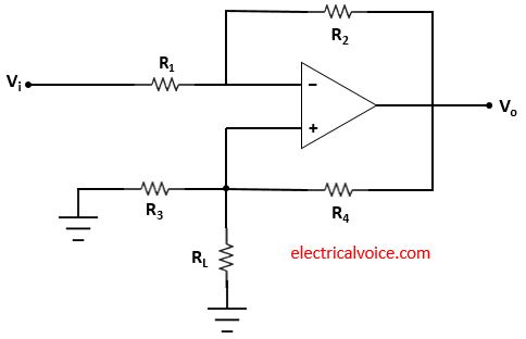
Ground load voltage to current converter circuit 2 as shown in figure 5. The input Vi is applied as shown in figure 5. Vo is the output voltage. The resistance R3 connected to the non-inverting terminal of the op-amp is grounded. The load resistor (RL) is grounded in this V-I converter circuit. It is said to be grounded because the load resistance is connected to the ground.
Analysis
The analysis of the V-I converter circuit is shown in figure 6. Let the voltage of node Q is V1. Since the op-amp is ideal and negative feedback is present, the voltage of the inverting terminal (V−) is equal to the voltage of the non-inverting terminal (V+ = V1), according to the virtual short concept.
V− = V+ = V1
The currents entering both terminals of the op-amp are zero since the op-amp is ideal.
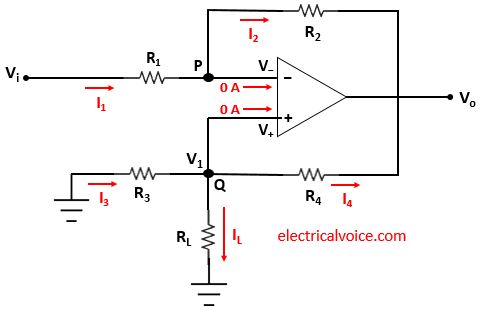
Let current I1 and I2 flows through the resistor R1 and R2 respectively.
\begin{equation} \label{eq:poly}
I_1=\frac{V_{i}-V_{1}}{R_1}
\end{equation}
\begin{equation} \label{eq:poly}
I_2=\frac{V_{1}-V_{o}}{R_2}
\end{equation}
Apply KCL at node P
$I_{1} = 0 + I_2$
\begin{equation} \label{eq:poly}
I_1 = I_{2}
\end{equation}
From equations (10), (11), and (12), we have
\begin{equation} \label{eq:poly}
\frac{V_{i}-V_1}{R_1}=\frac{V_{1}-V_{o}}{R_2}
\end{equation}
$\frac{V_i}{R_1}+\frac{V_o}{R_2}=V_1(\frac{1}{R_1}+\frac{1}{R_2})$
or we can write it as
\begin{equation} \label{eq:poly}
$V_1=\frac{\frac{V_i}{R_1}+\frac{V_o}{R_2}}{\frac{1}{R_1}+\frac{1}{R_2}}$
\end{equation}
The current I3 , I4 and IL flows through the resistor R3 , R4 and RL respectively.
\begin{equation} \label{eq:poly}
I_3=\frac{0-V_{1}}{R_3}=-\frac{V_{1}}{R_3}
\end{equation}
\begin{equation} \label{eq:poly}
I_4=\frac{V_{1}-V_{o}}{R_4}
\end{equation}
Apply KCL at node Q
$I_{3} = 0 + I_4 + I_L$
\begin{equation} \label{eq:poly}
I_3 = I_{L}+I_4
\end{equation}
From equations (15), (16), and (17), we have
$\Rightarrow -\frac{V_{1}}{R_3}=I_L+\frac{V_{1}-V_{o}}{R_4}$
put value of $V_{1}-V_{o}$ from equation (13), we have
$\Rightarrow -\frac{V_{1}}{R_3}=I_L+(V_i-V_1)\frac{R_2}{R_1R_4}$
$\Rightarrow I_L=-\frac{V_i}{\frac{R_1R_4}{R_2}}+V_1\frac{R_2}{R_1R_4}-\frac{V_1}{R_3}$
$\Rightarrow I_L=-\frac{V_i}{\frac{R_1R_4}{R_2}}+V_1(\frac{R_2}{R_1R_4}-\frac{1}{R_3})$
$\Rightarrow I_L=-\frac{V_i}{\frac{R_1R_4}{R_2}}+(\frac{\frac{V_i}{R_1}+\frac{V_o}{R_2}}{\frac{1}{R_1}+\frac{1}{R_2}})(\frac{R_2}{R_1R_4}-\frac{1}{R_3})$
If $\frac{R_2}{R_1}=\frac{R_4}{R_3}$
Then
$\Rightarrow I_L=-\frac{V_i}{\frac{R_4}{\frac{R_2}{R_1}}}$
$\Rightarrow I_L=-\frac{V_i}{\frac{R_4}{\frac{R_4}{R_3}}}$
$\Rightarrow I_L=-\frac{V_{i}}{R_3}$
\[
\quicklatex{color=”#000000″ size=20}
\boxed{I_L=-\frac{V_{i}}{R_3}}
\]
If input voltage Vi and Resistance (R3) is fixed then the load current (IL) is independent of the load resistance (RL).
V-I Converter Applications
This converter has applications in the following
1. Low voltage ac and dc voltmeters
2. LED and Zener diode testers
3. Diode match finders
