A non inverting amplifier is an operational amplifier circuit which produces an amplified output signal which is in phase with the input signal.
Non Inverting operational amplifier
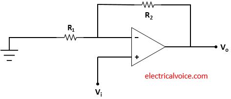
Figure 1 shows the basic non-inverting operational amplifier. The input signal Vi is applied directly to the non-inverting terminal while one side of resistor R1 is connected to the inverting terminal and the other side is at the ground.

Analysis
Case-1: When op-amp is ideal i.e. open-loop gain is infinite.
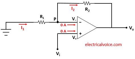
The analysis of the non-inverting amplifier circuit is shown in figure 2. Since the op-amp is ideal and negative feedback is present, the voltage of the inverting terminal (V−) is equal to the voltage of the non-inverting terminal (V+ = Vi), according to the virtual short concept.
V− = V+ = Vi
The currents entering both terminals of the op-amp are zero since the op-amp is ideal.

\begin{equation} \label{eq:poly}
I_1=\frac{0-V_i}{R_1}=-\frac{V_i}{R_1}
\end{equation}
\begin{equation} \label{eq:poly}
I_2=\frac{V_i-V_o}{R_2}
\end{equation}
Apply KCL at node P
$I_{1} = 0 + I_2$
\begin{equation} \label{eq:poly}
I_1= I_{2}
\end{equation}
From equations (1), (2) and (3), we have
$\Rightarrow -\frac{V_i}{R_1}=\frac{V_i-V_o}{R_2}$
$\Rightarrow \frac{V_0}{R_2}=V_i[\frac{1}{R_1}+\frac{1}{R_2}]$
The closed-loop voltage gain Av is given by
\[
\quicklatex{color=”#000000″ size=20}
\boxed{A_{v}=\frac{V_0}{V_i}=1+\frac{R_2}{R_1}}
\]
From voltage gain Av, we can see that the output is in phase with the input. Another conclusion can be drawn from the above equation is that the gain is always greater than unity.
The input signal Vi is connected directly to the non-inverting terminal and the input current is essentially zero (ideal op-amp), the input impedance (or Resistance) seen by the source is very large (ideally infinite).
Case-2: When op-amp has a finite open-loop gain, AOL (Practical case)
The analysis of the non inverting amplifier circuit is shown in figure 3. Since the op-amp has a finite open-loop gain, Hence the voltage of the inverting terminal (V−) is not equal to the voltage of the non-inverting terminal (V+ = 0) i.e.
V− ≠ V+
Assuming that the currents entering both terminals of the op-amp are zero.

\begin{equation} \label{eq:poly}
I_1=\frac{0-V_-}{R_1}=-\frac{V_-}{R_1}
\end{equation}
\begin{equation} \label{eq:poly}
I_2=\frac{V_–V_o}{R_2}
\end{equation}
Apply KCL at node P
$I_{1} = 0 + I_2$
\begin{equation} \label{eq:poly}
I_1= I_{2}
\end{equation}
From equations (4), (5) and (6), we have
$\Rightarrow -\frac{V_-}{R_1}=\frac{V_–V_o}{R_2}$
$\Rightarrow \frac{V_0}{R_2}=V_-[\frac{1}{R_1}+\frac{1}{R_2}]$
$\Rightarrow V_o=[1+\frac{R_2}{R_1}]V_-$
\begin{equation} \label{eq:poly}
V_-=\frac{V_o}{[1+\frac{R_2}{R_1}]}
\end{equation}
As we know that,
$V_o=A_{OL}(V_+-V_-)$
\begin{equation} \label{eq:poly}
V_o=A_{OL}(V_i-V_-)
\end{equation}
From equations (7) and (8), we have
$V_o=A_{OL}[V_i-\frac{V_o}{(1+\frac{R_2}{R_1})}]$
$\Rightarrow \frac{V_o}{A_{OL}}+\frac{V_o}{(1+\frac{R_2}{R_1})}=V_i$
$\Rightarrow V_o[\frac{1}{A_{OL}}+\frac{1}{(1+\frac{R_2}{R_1})}]=V_i$
The closed-loop voltage gain Av is given by
$\Rightarrow A_v=\frac{V_o}{V_i}=\frac{1}{\frac{1}{A_{OL}}+\frac{1}{(1+\frac{R_2}{R_1})}}$
Therefore, we can also write it as
\[
\quicklatex{color=”#000000″ size=20}
\boxed{A_v=\frac{V_o}{V_i}=\frac{(1+\frac{R_2}{R_1})}{1+\frac{(1+\frac{R_2}{R_1})}{A_{OL}}}}
\]
From voltage gain Av, we can see that the output is in phase with the input.
Important points to Remember
1. The closed-loop voltage gain Av of the non-inverting operational amplifier also depends on the values of R2 & R1
2. The closed-loop voltage gain Av of a non-inverting amplifier is greater than unity.
3. The output signal is in phase with the input signal as the closed-loop voltage gain Av is positive.
4. Since output and input are in the same phase hence phase shift is zero.
Non inverting amplifier applications
1. It is used where the amplified output required in phase with the input.
2. It can be used for performing mathematical stimulation such as an adder.

thanks so much for your support through the provision of online notes
I always enjoy your provisions