An operational amplifier popularly known as op-amp is a DC-coupled high gain electronic voltage amplifier with a differential input and usually a single-ended output.
As the name suggests, it is basically an amplifier, whose job is to amplify the input signals. The reason behind it being called as “operational” is that, in early days when digital computers were not evolved, at that time, the basic “mathematical operations” like addition, subtraction, differentiation and integration were performed by them. Today, operational amplifiers have become a popular building block in electronic circuits.
As said earlier, the operational amplifier has two inputs and a single output. The schematic representation of the op-amp is shown below.
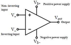
The positive terminal of the input is called the “non-inverting” input and the negative terminal is called the “inverting” input. They have their names according to the functions performed by them.
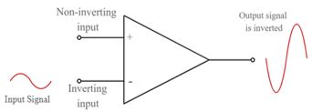
Inverting Input: A positive voltage applied to this input terminal will lead to a negative swing at the output.
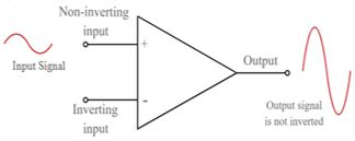
Non-Inverting Input: A positive voltage applied to this input terminal will lead to a positive swing at the output.
The output voltage is proportional to the difference of the input voltages and is given by
Vout ∝ (V+ – V–)
Vout = AOL (V+ – V–)
where, AOL is the open-loop gain of the amplifier.
Pin Diagram
IC-741 is a general-purpose op-amp. It is built of various resistors, capacitors and transistor stages. Three main stages of a general-purpose op-amp are a differential input stage, a push-pull output stage and an intermediate gain stage.
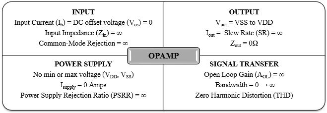
Ideally, the pin description can be divided into 4 broad categories:
Pin diagram of IC-741 is shown in the figure 4. This is a general-purpose operational amplifier. It has a total of 8 pins.
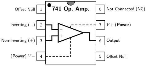
Pin Description
» Pin4 & Pin7 (Power Supply): Pin7 is the positive voltage supply terminal and Pin4 is the negative voltage supply terminal. The IC draws in power from these pins. The voltage between these two pins lies between 5V and 18V.
» Pin6 (Output): This is the output pin for the IC. The voltage at this pin depends on the input signal and the feedback mechanism used.
» Pin2 & Pin3 (Input): These are input pins. Pin2 is the inverting input and Pin3 is the non-inverting input. If the voltage at inverting input is higher than non-inverting input, the voltage at the output signal stays low. Likewise, if the voltage at the non-inverting input is high, the output goes high.
» Pin1 & Pin5 (Offset Null): Because of high gain provided by Op-Amp, even slight variations in voltages at the inverting and non-inverting inputs, caused due to irregularities in the manufacturing process or external disturbances, will affect the output. To nullify this effect, an offset voltage can be applied at pin1 and pin5 and is typically done employing a potentiometer.
» Pin8 (N/C): This pin is not connected to any circuit inside 741 IC. It’s just a dummy lead used to fill the void space in standard 8 pin packages.
The following are the basic specifications of 741 IC:
• Power Supply: needs a minimum voltage of 5V and might face up to 18V
• Input Impedance: ~2 MΩ
• Output impedance: ~75Ω
• Slew Rate: 0.5V/µs
• Maximum Output Current: 20mA
• Recommended Output Load: >2 kΩ
• Input Offset: Between 2mV and 6mV
• Voltage Gain: 200,000 for low frequencies
Working Principle
1. Open Loop Operation
An ideal op-amp amplifies the difference between the two applied input signals (i.e. at the inverting and the non-inverting) signals. This difference between the two input signals is called the differential input voltage. The equation below gives the output of an operational amplifier.
Vout = AOL (V+ – V–)
where, AOL = open-loop gain (means, the gain of the op-amp component all by itself, with all the different components removed significantly with the feedback element removed).
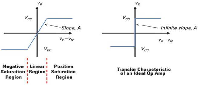
In open loop, the op-amp can work only as a comparator. The open-loop gain of an op-amp is very high. Hence, an open-loop operational amplifier amplifies a small applied differential input voltage to a huge value, but this significant value at the output cannot go beyond the supply voltage of the op-amp. Hence it does not violate the law of conservation of energy.
2. Closed-Loop Operation
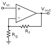
Feedback is introduced in the closed-loop configuration. This feedback path feeds the output signal back to the input. Hence, at the inputs, two signals are simultaneously present. One of them is the original applied signal, and the other is the feedback signal. The equation below shows the output of a closed-loop op-amp.
Vout = ACL (V+ – V–)
where, ACL is the closed-loop gain. The feedback circuit connected to the op-amp determines the closed-loop gain ACL.
Feedback is said to be positive if the feedback path feeds the signal from the output terminal back to the non-inverting (+) terminal. Positive feedback is used in oscillators. The feedback is negative if the feedback path feeds the part of the signal from the output terminal back to the inverting (-) terminal. Negative feedback to the op-amps is used in amplifiers.
Op-Amp Characteristics
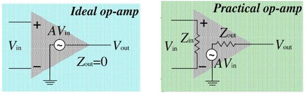
» Input Impedance (Zin)
It is the ratio of input voltage to the input current. It is assumed to be infinite to prevent any current flowing from the supply into the op-amp circuit (Iin=0). An ideal op-amp has infinite input impedance. But practically, when op-amp is used in linear applications, some negative feedback is provided. Due to this negative feedback, the input impedance becomes:
Zin = (1 + AOL β) Zi
where, Zi = input impedance without feedback
AOL = open-loop gain
β = feedback factor
» Output Impedance (Zout)
An ideal op-amp has zero output impedance acting as a perfect internal voltage source with zero internal resistance, so that maximum current can be driven to the load. Practically, the output impedance of the op-amp is given by:
![]()
where, Zo = output impedance of op-amp without feedback
AOL = open-loop gain
β = feedback factor
» Open-Loop Gain (AOL)
It is defined as the gain of the op-amp when there is no feedback in the circuit. For an ideal op-amp, the gain will be infinite, but practically the value ranges from 20,000 to 200,000.
» Bandwidth (BW)
Ideally, an op-amp can amplify any frequency signal from DC to the highest AC frequencies, thus it has an infinite frequency response. Hence the bandwidth of an ideal op-amp should be infinite but practically it is limited by the Gain-Bandwidth product (GB).
» CMRR (Common Mode Rejection Ratio)
CMRR is defined as the ratio of the change to the output voltage with regards to the change in the common-mode input voltage. It is basically the ability of an op-amp to reject the common-mode input signal. An ideal op-amp will have infinite CMRR, but practically, it is given by:
![]()
where, AD = differential gain of the op-amp
AC = common-mode gain of the op-amp
» Input Offset Voltage (VIO)
Input offset voltage is the voltage that is applied between the two input terminals of the op-amp to nullify the output. Ideally, op-amps shall have zero offset voltage, but practically they show some small offset.
» Input Offset Current (IIO)
Input Offset Current is the algebraic difference between the currents into the inverting and non-inverting terminals.
![]()
where, Ib1 = Non-inverting input current and Ib2 = Inverting input current
Ideally, it shall be zero. Practically, it lies between 200nA to 6nA.
» Slew Rate
Slew rate is the maximum rate at which an amplifier can respond to an abrupt change of input level. It is defined as the rate of change of output voltage per unit time. It is measured typically in V/µs or V/ms.
An ideal op-amp will have an infinite slew rate. In practical op-amps, the slew rate is limited by the small internal drive currents and the internal capacitances of the op-amp.
Ideal vs. Practical Characteristics of Op-amp
| S.No. | Property | Ideal Op-amp | Practical Opamp |
| 1. | Input impedance | Infinite | High (>1MΩ) |
| 2. | Output impedance | Zero | Low (<100Ω) |
| 3. | Open-loop gain | Infinite | High (>10000) |
| 4. | Bandwidth | Infinite | Dominant pole (~10 Hz) |
| 5. | CMRR | Infinite | High(>60dB) |
| 6. | Input offset voltage | Zero | Low (<10mV) |
| 7. | Input offset current | Zero | Low(<50nA) |
| 8. | Slew Rate | Infinite | Few V/µs |
Concept of Virtual Short
As the name suggests it is basically a “short” between two points that is imaginary. In the context of an op-amp, virtual short means, the voltage at inverting terminal (V–) tracks the voltage at the non-inverting terminal (V+) under NEGATIVE feedback. (i.e., V– = V+). There is no physical connection between the two terminals; rather it is just an imaginary connection.
Actually, this is not one of the fundamental characteristics of an ideal operational amplifier. Rather, the virtual short is a theoretical situation that arises from one of the fundamental characteristics of an ideal op-amp, namely, infinite open-loop gain.
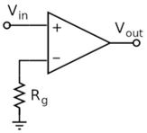
We know that,![]()
As ideal gain is infinite, hence Vin = 0 [Vin = V+ – V–]
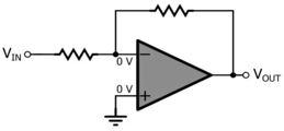
As shown in the figure, V+ is connected to ground, so V+ = 0. Hence, V– will also be at ground potential.
This concept is used for easy analysis of op-amp based circuits (with negative feedback). However, the concept of virtual short is not applicable even in the negative feedback circuit if the loop gain is not very large.
In positive feedback difference between non-inverting and inverting terminals does not decrease, instead, it keeps increasing and makes the op-amp sit at positive saturation. So, in positive feedback virtual short is not applicable.
However, there are some other applications which use negative and positive feedback at the same time. In such circuits, as long as the negative feedback is dominating, the circuit remains stable and the “virtual short” principle is applicable.
Applications of operational amplifier
Operational amplifiers are popular building blocks in electronic circuits. They find applications in most of the consumer and industrial electronic systems.
Operational amplifiers can be configured to work as inverting amplifiers, non-inverting amplifiers; to perform mathematical operations like addition, subtraction, multiplication, division, differentiation and integration. It can also be used in the construction of filters (high-pass, low-pass, band-pass, and band-reject). If required, an open-loop op-amp can be forced to act as a comparator.
Operational amplifiers with positive feedback can be used in the construction of oscillators. They are also used in non-linear circuits such as logarithmic and anti-logarithmic amplifiers.
Operational amplifiers also discover applications as Voltage sources, Current sources, and Current sinks and furthermore as DC and AC Voltmeters. Op-amps are additionally utilized in signal handling circuits, for example, Sample-and-Hold circuits, Precision Rectifier and Clamping circuits.
Few of the applications of the op-amp are
4. Integrator
About Author