Current to Voltage Converter or I-V converter is an electronic circuit that produces a voltage that is proportional to the applied input current. It is used where we need to measure the output current but the measuring instrument is capable of measuring voltages only. In this article, we will see the op-amp based I-V converter, its working and its applications.
Current to Voltage Converter

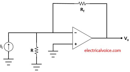
Current to voltage converter circuit as shown in figure 1. The input current Ii is applied as shown in figure 1. Vo is the output voltage. The resistance R connected to the inverting terminal of the op-amp is grounded. The non-inverting terminal of the op-amp is grounded. The resistor (Rf) is floating in this I-V converter circuit. It is said to be floating because the resistance is not connected to the ground.
Analysis
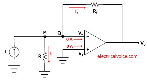
The analysis of the I-V converter circuit is shown in figure 2. Since the op-amp is ideal and negative feedback is present, the voltage of the inverting terminal (V−) is equal to the voltage of the non-inverting terminal (V+ = 0), according to the virtual ground concept.
V− = V+ = 0 Volt
The currents entering both terminals of the op-amp are zero since the op-amp is ideal.

\begin{equation} \label{eq:poly}
I=\frac{0-0}{R}=0 A
\end{equation}
Apply KCL at node Q
$I_{i} = 0 + I_f$
\begin{equation} \label{eq:poly}
I_f = I_{i}
\end{equation}
\begin{equation} \label{eq:poly}
I_f=\frac{0-V_o}{R_f}=-\frac{V_o}{R_f}
\end{equation}
From equations (2) and (3), we have
$I_{i}=-\frac{V_o}{R_f}$
\[
\quicklatex{color=”#000000″ size=20}
\boxed{V_o=-R_fI_i}
\]
As we can see from the above equation, voltage produce at the output is proportional to the applied input current.
Note: The lower limit on current measurement with this I-V converter circuit is set by the bias current of the inverting input.
Applications
1. This circuit is used for measuring light intensity using a photodiode sensor. The output of a photodiode sensor used in this circuit is a current which changes proportionally to the light intensity. Another advantage of using op-amp is that the voltage across photodiode remains at 0 volts.
If you need help with your electrical engineering assignments from experts, feel free to contact MyAssignmentLab and find someone to do your homework for you online.
