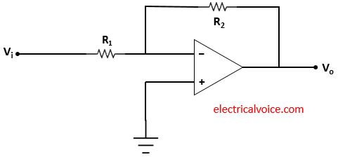
An inverting amplifier is an operational amplifier circuit which produces amplified output that is 180° out of phase to the applied input. Inverting amplifier is also known as inverting operational amplifier or inverting op-amp.
Inverting operational amplifier
Figure 1 shows the basic inverting operational amplifier. The input signal Vi is applied to the inverting terminal through the R1 resistor. The non-inverting terminal of the op-amp is grounded.

Analysis
Case-1: When op-amp is ideal i.e. open-loop gain is infinite.
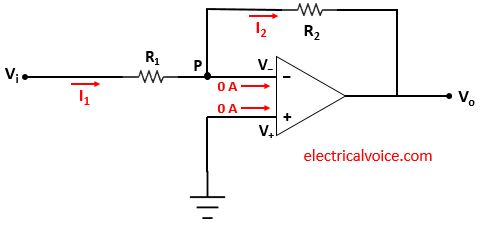
The analysis of the inverting amplifier circuit is shown in figure 2. Since the op-amp is ideal and negative feedback is present, the voltage of the inverting terminal (V−) is equal to the voltage of the non-inverting terminal (V+ = 0), according to the virtual ground concept.
V− = V+ = 0 Volt
The currents entering both terminals of the op-amp are zero since the op-amp is ideal.

\begin{equation} \label{eq:poly}
I_1=\frac{V_i-0}{R_1}=\frac{V_i}{R_1}
\end{equation}
\begin{equation} \label{eq:poly}
I_2=\frac{0-V_o}{R_2}=-\frac{V_o}{R_2}
\end{equation}
Apply KCL at node P
$I_{1} = 0 + I_2$
\begin{equation} \label{eq:poly}
I_1= I_{2}
\end{equation}
From equations (1), (2) and (3), we have
$\Rightarrow \frac{V_i}{R_1}=-\frac{V_o}{R_2}$
$\Rightarrow \frac{V_0}{V_i}=-\frac{R_2}{R_1}$
The closed-loop voltage gain Av is given by
\[
\quicklatex{color=”#000000″ size=20}
\boxed{A_{v}=\frac{V_0}{V_i}=-\frac{R_2}{R_1}}
\]
From voltage gain Av, we can see that the output is 180° out of phase with the input.
Case-2: When op-amp has a finite open-loop gain, AOL (Practical case)
The analysis of the inverting amplifier circuit is shown in figure 3. Since the op-amp has a finite open-loop gain, Hence the voltage of the inverting terminal (V−) is not equal to the voltage of the non-inverting terminal (V+ = 0) i.e.
V− ≠ V+
Assuming that the currents entering both terminals of the op-amp are zero.

\begin{equation} \label{eq:poly}
I_1=\frac{V_i-V_-}{R_1}
\end{equation}
\begin{equation} \label{eq:poly}
I_2=\frac{V_–V_o}{R_2}
\end{equation}
Apply KCL at node P
$I_{1} = 0 + I_2$
\begin{equation} \label{eq:poly}
I_1= I_{2}
\end{equation}
From equations (4), (5) and (6), we have
$\Rightarrow \frac{V_i-V_-}{R_1}=\frac{V_–V_o}{R_2}$
\begin{equation} \label{eq:poly}
$\Rightarrow \frac{V_i}{R_1}=-\frac{V_o}{R_2}+V_-(\frac{1}{R_1}+\frac{1}{R_2})$
\end{equation}
As we know that,
$V_o=A_{OL}(V_+-V_-)$
$V_o=A_{OL}(0-V_-)=-A_{OL}V_-$
\begin{equation} \label{eq:poly}
V_-=-\frac{V_0}{A_{OL}}
\end{equation}
From equations (7) and (8), we have
$\Rightarrow \frac{V_i}{R_1}=-\frac{V_o}{R_2}-\frac{V_0}{A_{OL}}(\frac{1}{R_1}+\frac{1}{R_2})$
$\Rightarrow \frac{V_i}{R_1}=-V_o(\frac{1}{R_2}+\frac{1}{A_{OL}}(\frac{1}{R_1}+\frac{1}{R_2}))$
The closed-loop voltage gain Av is given by
$\Rightarrow A_v=\frac{V_o}{V_i}=\frac{-\frac{1}{R_1}}{\frac{1}{R_2}+\frac{1}{A_{OL}}(\frac{1}{R_1}+\frac{1}{R_2})}$
$\Rightarrow A_v=\frac{V_o}{V_i}=\frac{-\frac{R_2}{R_1}}{1+\frac{1}{A_{OL}}(1+\frac{R_2}{R_1})}$
Therefore
\[
\quicklatex{color=”#000000″ size=20}
\boxed{A_v=\frac{V_o}{V_i}=\frac{-\frac{R_2}{R_1}}{1+\frac{(1+\frac{R_2}{R_1})}{A_{OL}}}}
\]
From voltage gain Av, we can see that the output is 180° out of phase with the input.
