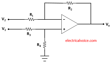
A differential amplifier is an op amp circuit which is designed to amplify the difference input available and reject the common-mode voltage. It is used for suppressing the effect of noise at the output. Since the noise present will be having the same amplitude at the two terminals of the op-amp. So when the difference between terminals is taken, the noise will cancel each other. The differential amplifier output is proportional to the difference of the input terminals. Hence the output is free from noise.
Differential amplifier
Figure 1 shows the basic differential amplifier. The two input signal V1 and V2 are applied to the op amp.

Working
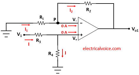
Apply superposition theorem to find out the output voltage. First of all, deactivate V2 and connect it to ground as shown in figure 2.

Applying voltage division method
\begin{equation} \label{eq:poly}
V_+ = \frac{R_4}{R_3+R_4}V_1
\end{equation}
Since the op-amp is ideal and negative feedback is present, the voltage of the inverting terminal (V−) is equal to the voltage of the non-inverting terminal (V+), according to the virtual short concept.
V− = V+
The currents entering both terminals of the op-amp are zero since the op-amp is ideal.
\begin{equation} \label{eq:poly}
I_1=\frac{0-V_+}{R_1}=-\frac{V_+}{R_1}
\end{equation}
\begin{equation} \label{eq:poly}
I_2=\frac{V_+-V_{o1}}{R_2}
\end{equation}
Apply KCL at node P
$I_{1} = 0 + I_2$
\begin{equation} \label{eq:poly}
I_1= I_{2}
\end{equation}
From equations (2), (3) and (4), we have
$\Rightarrow -\frac{V_+}{R_1}=\frac{V_+-V_{o1}}{R_2}$
$\Rightarrow \frac{V_{o1}}{R_2}=V_+[\frac{1}{R_1}+\frac{1}{R_2}]$
From equation 1, we have
\begin{equation} \label{eq:poly}
V_{o1}=(1+\frac{R_2}{R_1})(\frac{R_4}{R_3+R_4})V_1
\end{equation}
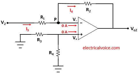
Now deactivate V1 and connect it to ground as shown in figure 3.

As we can see that the voltage across R4 is zero. Therefore V+ = 0 V. Since the op-amp is ideal and negative feedback is present, the voltage of the inverting terminal (V−) is equal to the voltage of the non-inverting terminal (V+ = 0), according to the virtual ground concept.
V− = V+ = 0 Volt
The currents entering both terminals of the op-amp are zero since the op-amp is ideal.
\begin{equation} \label{eq:poly}
I_1=\frac{V_2-0}{R_1}=\frac{V_2}{R_1}
\end{equation}
\begin{equation} \label{eq:poly}
I_2=\frac{0-V_{o2}}{R_2}=-\frac{V_{o2}}{R_2}
\end{equation}
Apply KCL at node P
$I_{1} = 0 + I_2$
\begin{equation} \label{eq:poly}
I_1= I_{2}
\end{equation}
From equations (6), (7) and (8), we have
$\Rightarrow \frac{V_2}{R_1}=-\frac{V_{o2}}{R_2}$
$\Rightarrow V_{o2}=-\frac{R_2}{R_1}V_2$
\begin{equation} \label{eq:poly}
V_{o2}=-\frac{R_2}{R_1}V_2
\end{equation}
Adding equations (5) and (9), we get the output voltage Vo
$V_o=V_{o1}+V_{o2}$
\begin{equation} \label{eq:poly}
V_o=(1+\frac{R_2}{R_1})(\frac{R_4}{R_3+R_4})V_1-\frac{R_2}{R_1}V_2
\end{equation}
\begin{equation} \label{eq:poly}
V_o=\frac{R_4}{R_3}(1+\frac{R_2}{R_1})(\frac{1}{1+\frac{R_4}{R_3}})V_1-\frac{R_2}{R_1}V_2
\end{equation}
Case-1: when $\frac{R_2}{R_1}=\frac{R_4}{R_3}$
then
$V_o=\frac{R_2}{R_1}(1+\frac{R_2}{R_1})(\frac{1}{1+\frac{R_2}{R_1}})V_1-\frac{R_2}{R_1}V_2$
$\Rightarrow V_o=\frac{R_2}{R_1}(1+\frac{R_2}{R_1})(\frac{1}{1+\frac{R_2}{R_1}})V_1-\frac{R_2}{R_1}V_2$
The output Vo is
\[
\quicklatex{color=”#000000″ size=20}
\boxed{V_o=\frac{R_2}{R_1}(V_1-V_2)}
\]
Now
$V_d=V_1-V_2$
and
$V_c=\frac{V_1+V_2}{2}$
The output Vo is given by
$V_o=A_dV_d+A_cV_c$
where Ad = differential gain and Ac = common mode gain
As $V_o=\frac{R_2}{R_1}(V_1-V_2)$
Therefore, we have
$A_d=\frac{R_2}{R_1}$ and $A_c=0$
so $V_o=A_dV_d$
Common mode rejection ratio (CMRR)
\[CMRR=\left | \frac{A_d}{A_c} \right |\]
using above value of Ad and Ac, we have
\[CMRR=\left | \frac{\frac{R_2}{R_1}}{0} \right |=\infty\]
Note: Ideally CMRR is infinite. So CMRR value for this circuit to be infinite, $\frac{R_2}{R_1}=\frac{R_4}{R_3}$.
Case2: when $\frac{R_2}{R_1}\neq\frac{R_4}{R_3}$
since
$V_d=V_1-V_2$
and
$V_c=\frac{V_1+V_2}{2}$
then we can write it as
$V_1=V_c+\frac{V_d}{2}$
and
$V_2=V_c-\frac{V_d}{2}$
Therefore equation (10) becomes
$V_o=(1+\frac{R_2}{R_1})(\frac{R_4}{R_3+R_4})(V_c+\frac{V_d}{2})-\frac{R_2}{R_1}(V_c-\frac{V_d}{2})$
\begin{equation} \label{eq:poly}
V_o=\frac{V_d}{2}[(1+\frac{R_2}{R_1})(\frac{R_4}{R_3+R_4})+\frac{R_2}{R_1}]+V_c[(1+\frac{R_2}{R_1})(\frac{R_4}{R_3+R_4})-\frac{R_2}{R_1}]
\end{equation}
\begin{equation} \label{eq:poly}
$V_o=A_dV_d+A_cV_c$
\end{equation}
Comparing equation (12) and (13), we have
$A_d=\frac{1}{2}[(1+\frac{R_2}{R_1})(\frac{R_4}{R_3+R_4})+\frac{R_2}{R_1}]$
and
$A_c=[(1+\frac{R_2}{R_1})(\frac{R_4}{R_3+R_4})-\frac{R_2}{R_1}]$
Then CMRR is given as
$CMRR=\left | \frac{A_d}{A_c} \right |$
$\Rightarrow CMRR=\left | \frac{\frac{1}{2}[(1+\frac{R_2}{R_1})(\frac{R_4}{R_3+R_4})+\frac{R_2}{R_1}]}{[(1+\frac{R_2}{R_1})(\frac{R_4}{R_3+R_4})-\frac{R_2}{R_1}]} \right |$
\[
\quicklatex{color=”#000000″ size=20}
\boxed{CMRR=\left | \frac{\frac{1}{2}[(1+\frac{R_2}{R_1})(\frac{R_4}{R_3+R_4})+\frac{R_2}{R_1}]}{[(1+\frac{R_2}{R_1})(\frac{R_4}{R_3+R_4})-\frac{R_2}{R_1}]} \right |}
\]
Note: $(CMRR)_{dB}=20\log_{10}\left | \frac{A_d}{A_c} \right |$
Note: For a better differential amplifier, CMRR should be as high as possible.
Note: CMRR depends upon the circuit and not depend upon the applied input.
