Peak Detector is a circuit which is used to detect the peaks of the applied input signal. It basically follows the input voltage and stores the peak voltage. It employs a diode and capacitor to implement this function.
Types of Peak Detector
- Active peak detector
- Passive peak detector
Active peak detector
Active peak detectors use active components like op-amps, transistors, etc. It is more accurate as the losses incurred due to resistive elements are taken care of by the active components.
Passive peak detector
Passive peak detectors use passive components like diodes, capacitors, etc. It is less accurate because of the losses occurring in different elements mainly resistors.
Active Peak Detector Circuit
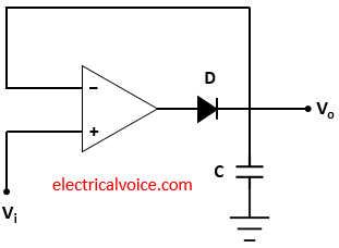
Figure 1 shows an active peak detector circuit. It consists of an op-amp, diode (D) and capacitor (C). Let us assume that all are ideal. Input (Vi) is applied to the non-inverting terminal of the op-amp. Vo is the output voltage.
Working
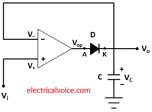
Figure 2 shows the working of the active peak detector circuit. The working principle of this circuit is that the peak of the input waveform is followed and stored in terms of voltage (Vc) across the capacitor.
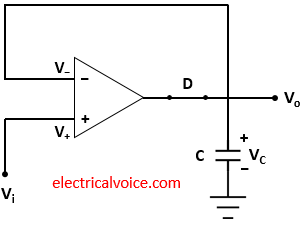
Whenever the input voltage is greater than the capacitor voltage Vc, the diode D will be ON and there will be the charging of the capacitor C. The circuit will be working as a non-inverting amplifier and capacitor voltage Vc follows input voltage Vi. The circuit for this case is shown in figure 3.
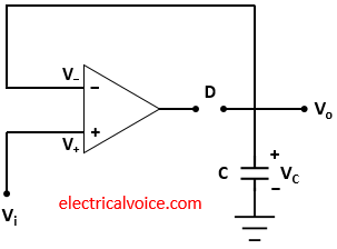
Whenever the input voltage Vi is lesser than the capacitor voltage Vc, the diode D will be OFF and the op-amp is working in an open-loop configuration. In this case, capacitor voltage Vc holds its previous maximum charged voltage until the input voltage Vi becomes more than this maximum voltage. The circuit for this case is shown in figure 4.
Let us understand this with an example. Consider the figure 5. Figure 5(a) shows the input voltage waveform and Figure 5(b) shows the capacitor or output voltage waveform. From figure 2 we can see that capacitor voltage Vc is equal to the output voltage Vo.

Assume that capacitor voltage Vc (Vc = Vo) is 0 initially. As the input voltage is applied to the non-inverting terminal, the diode D is turned ON and the capacitor voltage will follow the input waveform till time t2. At this time, Vi = V2. Therefore, Vo = Vc = V2. After time t2, the input voltage starts decreasing. As the cathode voltage is greater than the anode voltage, the diode is turned OFF. The capacitor will retain this maximum voltage till Vi is greater than the Vc (i.e. till time t3). After time t3, the Vc again follow the Vi till time t4. At this time, Vi = V3. Therefore, Vo = Vc = V3. After time t4, the input voltage starts decreasing. As the cathode voltage is greater than the anode voltage, the diode is turned OFF. The capacitor will retain this maximum voltage till Vi is greater than the Vc (i.e. till time t5). After time t5, the Vc again follow the Vi till time t6. At this time, Vi = V4. Similarly, the capacitor will charge up to the maximum voltage V5 and retain it until the next peak or maximum voltage comes. This how the active peak detector works.
Peak Detector Applications
1. It is used in ASK demodulation.
2. It is extensively used for low-frequency envelope detection in AM demodulation.
