A Bipolar Junction Transistor (BJT) is a current-controlled semiconductor device which has three-terminals. The current in BJT is carried by both majority and minority carriers so it is known as bipolar device. The input resistance of BJT is low so it is used as an amplifier, oscillator circuits and digital circuits.
Note: The usage of the term transistor in this article will be used for bipolar junction transistor (BJT).
Basic Construction of BJT
A BJT consists of two pn junctions so it is analogous to two back to back connected diodes as shown in fig 1.1. A transistor is classified into two types based on its construction.
1. NPN Transistor
2. PNP Transistor
A transistor in which a thin layer of n-type semiconductor is sandwiched between two layers of p-type semiconductor is known as PNP transistor. In PNP transistor charge carriers are holes. It is shown in fig 1.1.
A transistor in which a thin layer of p-type semiconductor is sandwiched between two layers of n-type semiconductor is known as NPN transistor. In NPN transistor charge carriers are electrons. It is shown in fig 1.1.

A transistor (NPN or PNP) consist of three regions of doped semiconductors, which are named as Emitter, Base and Collector.
1. Emitter is responsible to supply charge carriers (NPN-electrons or PNP-holes) in the transistor. The emitter-base junction is always forward biased so that it can supply large numbers of majority charge carriers to the Base. It is a heavily doped region.
2. Base is the middle thin region of a transistor. The base-emitter region is always forward biased so it offers a very low resistive path for the emitter circuit. The base-collector region is always reverse biased so it offers a high resistive path for the collector circuit. It is a lightly doped region of the transistor.
3. Collector is the other side of the transistor which collects the charge carriers. It is always reverse biased. The doping level of a collector is lying between the doping level of emitter and base. Collector area is larger than the emitter and base area.
(DOPING)EMITTER > (DOPING)COLLECTOR > (DOPING)BASE
(AREA)COLLECTOR > (AREA)EMITTER > (AREA)BASE
NOTE: When two practical diodes are connected back to back, it can’t work as a transistor because there is no bonding force in between the two diodes.
Transistor Symbols
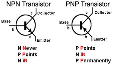
Fig 1.2 shows the symbols representation of NPN and PNP transistors. Arrow is always present on the emitter terminal and the direction of the arrow represents the flow of current due to charge carriers.
- In NPN transistor arrow shows the direction from p terminal to n terminal so the flow of current is from the base to emitter.
- In PNP transistor arrow shows the direction from p terminal to n terminal so the flow of current is from the emitter to base.
Trick to Remember Current Direction
NPN – NEVER POINTS IN
PNP – POINTS IN PERMANENTLY

Transistor Action
When we apply external voltage supply to the transistor this process is known as the biasing of the transistor. On the basis of the biasing transistor operates in the three different regions. The following table shows the different regions of operations on different biasing configurations.
| S.No. | E-B Junction | C-B Junction | Region of operation | Application |
| 1. | Forward-biased | Reverse-biased | Forward active mode | Amplifier |
| 2. | Forward-biased | Forward-biased | Saturation mode | Closed switch |
| 3. | Reverse-biased | Reverse-biased | Cut-off mode | Open switch |
| 4. | Reverse-biased | Forward-biased | Reverse active mode | —— |
1. Active region: In this region, the emitter-base region is forward biased and collector-base junction is reverse biased. A transistor in the active region is used for amplification. Collector current is dependent on the base current.
2. Saturation region: In this region, the emitter-base region is forward biased and collector-base junction is forward biased. Collector current is not dependent on the base current so transistor behaves like a closed switch.
3. Cut-off region: In this region both the junction is reverse biased. The current in transistor is zero because no charge carriers are emitted by emitter into the base regions and no charge carriers are collected by collector region. In this region, the transistor acts as an open switch.
4. Reverse active mode: In this region, junction E-B junction is reverse biased and the C-B junction is forward biased. A Transistor never operated in this mode.
Operation of NPN Transistor
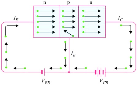
The base-emitter junction is forward biased by the dc source VEB and the collector-base junction is reverse biased by the VCB. So the depletion layer width at E-B junction is reduced and depletion layer width at the C-B junction is increased.
Operation: The operation of the NPN transistor as follows:
1. The forward biased E-B junction is forward biased so the majority charge carriers i.e. electrons start flowing toward the p-type base region as shown in fig. 1.3. This flow of charge carriers constitutes the Emitter current (IE).
2. As we know that the base region is very thin and lightly doped so the majority charge carriers i.e. holes is less in p-side. Hence the injected electrons into the base from emitter side get recombine with the holes of the base region. This constitutes base current (IB).

3. The remaining large number of electrons cross the base regions and move into the collector region and get attracted by the positive potential of the dc source VCB. This constitutes the collector current (IC).
Thus, the electron flow constitutes the dominant current in an NPN transistor. However, the emitter current is the sum of the base current and collector current.
IE = IB + IC
Operation of PNP Transistor
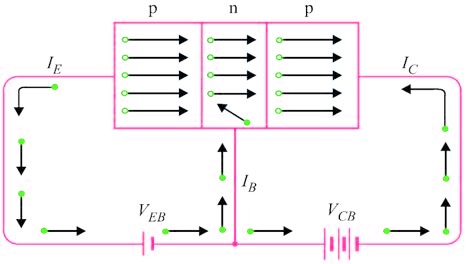
The base-emitter junction is forward biased by the dc source VEB and the collector-base junction is reversed biased by dc source VCB. Hence the depletion layer width of E-B junction is very less and that of C-B junction is large.
Operation: The operation of PNP transistor is as follows:
1. The forward biased E-B junction is forward biased so the majority charge carriers i.e. holes start flowing toward the n-type base region as shown in fig. 1.4. This flow of charge carriers constitutes the Emitter current (IE).
2. As we know that the base region is very thin and lightly doped so the majority charge carriers i.e. electrons is less in n-side. Hence the injected holes into the base from emitter side get recombine with the electrons of the base region. This constitutes base current (IB).

3. The remaining large number of holes cross the base regions and move into the collector region and get attracted by the negative potential of the dc source VCB. This constitutes the collector current (IC).
Thus, the hole flow constitutes the dominant current in a PNP transistor. However, the emitter current is the sum of the base current and collector current.
IE = IB + IC
Comparison between NPN and PNP Transistor
| S.No. | Parameters | NPN-Transistor | PNP-Transistor |
| 1. | Definition | Transistor in which two n-type semiconductor layers are separated by a p-type semiconductor layer. | Transistor in which two p-type semiconductor layers are separated by an n-type semiconductor layer. |
| 2. | Symbol |
|
|
| 3. | Current direction | Collector to Emitter | Emitter to Collector |
| 4. | Turn on | When electrons enter into the base | When holes enter into the base |
| 5. | Majority charge carriers | Electrons | Holes |
| 6. | Switching speed | Faster | Slower |
| 7. | Minority charge carriers | Holes | Electrons |
| 8. | Positive voltage | Collector Terminal | Emitter terminal |
Important Points to Remember
- BJT is a current controlled device.
- It has low input resistance.
- It is a bipolar device.
- Noisier device.
- Leakage current is existing so thermal stability is less.
- Gain is large.
- Gain bandwidth product (GBW) is constant.
- (BJT)GBW > (FET)GBW
- Higher power dissipation.
- The conductivity of the base is much smaller than the emitter.
- Major application as an amplifier.
About Author


Thanks l found this very useful – just enough detail to carry on without losing hope !!