A Shockley diode is a two terminal, three junction, four-layer p-n-p-n semiconductor device. It consists of four alternate p-type and n-type semiconductor layers in a single crystal. It was invented by William Shockley. It is used primarily for switching applications. It is similar to a thyristor with detached gate.
Shockley Diode Symbol
The schematic diagram of Shockley Diode is shown in figure 1. It is equivalent to three junction diodes connected in series as shown in figure 2. The symbol of Shockley Diode is shown in figure 3. Here A terminal represents the anode and K terminal represents the cathode.


Shockley Diode Working
(i) Under Forward biased
When this diode is forward biased (i.e., anode is positive w.r.t. cathode), junctions J1 and J3 would be forward biased while junction J2 would be reverse biased. Hence, it offers a very high resistance to the current flow.
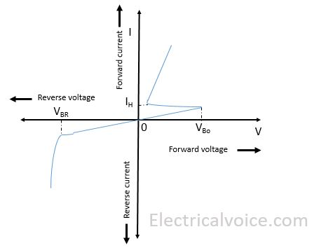
As the forward voltage increases, the reverse bias across junction J2 is also increased. At some forward voltage (called breakover voltage VBo), reverse breakdown of junction J2 occurs. Since this breakdown results in reduced resistance, this diode presents a very low resistance. Therefore it turns into conduction mode and acts as a closed switch thereby current starts flowing through it.
(ii) Under Reversed biased
When this diode is reversed biased (i.e., anode is negative w.r.t. cathode), junctions J1 and J3 would be reverse biased while junction J2 would be forward biased. If reverse voltage is increased sufficiently, the reverse voltage reaches the reverse breakdown voltage (VBR). At this voltage, junctions J1 and J3 would go into reverse voltage breakdown. The reverse current flowing through them would rise rapidly and the heat produced by this current flow could burn the whole device. For this reason, Shockley diode should never be operated with a reverse voltage greater than reverse voltage breakdown.
I-V characteristics of the Shockley diode
The I-V characteristics is shown in figure 4.

Note: To turn off the Shockley diode, the applied voltage is reduced to such a value so that current flowing through the device drops below its holding current (IH) value. The junction J2 then comes out of its reverse breakdown state and its high resistance value is restored.
Shockley diode applications
- It is used as a switch in the circuits to turn on an SCR.
- It finds application as a relaxation oscillator.
