Summing Amplifier is an electronic circuit that produces output as a weighted sum of the applied inputs. It is also known as Op-amp adder. Basically it performs mathematical operation of addition. In this article, we will see the summing amplifier circuit, its working and its applications.
Summing Amplifier Circuit

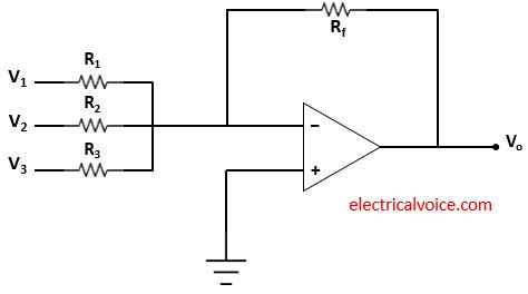
The summing amplifier circuit is shown in figure 1. The input V1 , V2, and V3 are applied. Vo is the output voltage. The non-inverting terminal of the op-amp is connected to the ground. This means that the voltage of the non-inverting terminal is zero volts.
Analysis
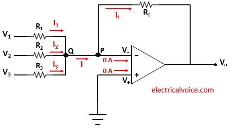
The analysis of the summing amplifier circuit is shown in figure 2. Since the op-amp is ideal and negative feedback is present, the voltage of the inverting terminal (V−) is equal to the voltage of the non-inverting terminal (V+ = 0V), according to the virtual short concept.
V− = V+ = 0V
The currents entering both terminals of the op-amp are zero since the op-amp is ideal.

The currents I1, I2 and I3 flowing through resistances R1, R2 and R3 respectively.
\begin{equation} \label{eq:poly}
I_1=\frac{V_{1}-0}{R_1}=\frac{V_{1}}{R_1}
\end{equation}
\begin{equation} \label{eq:poly}
I_2=\frac{V_{2}-0}{R_2}=\frac{V_{2}}{R_2}
\end{equation}
\begin{equation} \label{eq:poly}
I_3=\frac{V_{3}-0}{R_3}=\frac{V_{3}}{R_3}
\end{equation}
Apply KCL at node Q
\begin{equation} \label{eq:poly}
$I_1+I_2+I_3 = I$
\end{equation}
Apply KCL at node P
$I = 0+I_f$
\begin{equation} \label{eq:poly}
$I = I_f$
\end{equation}
\begin{equation} \label{eq:poly}
I_f=\frac{0-V_{o}}{R_f}=-\frac{V_{o}}{R_f}
\end{equation}
From equations (4), (5) and (6), we have
$\Rightarrow I_1+I_2+I_3=-\frac{V_{o}}{R_f}$
putting values of I1, I2 and I3 from equations (1), (2) and (3), we have
$\Rightarrow \frac{V_{1}}{R_1}+\frac{V_{2}}{R_2}+\frac{V_{3}}{R_3}=-\frac{V_{o}}{R_f}$
$\Rightarrow V_o=-(\frac{R_f}{R_1}V_1+\frac{R_f}{R_2}V_2+\frac{R_f}{R_3}V_3)$
Therefore,
\[
\quicklatex{color=”#000000″ size=20}
\boxed{V_o=-(\frac{R_f}{R_1}V_1+\frac{R_f}{R_2}V_2+\frac{R_f}{R_3}V_3)}
\]
If $R_1=R_2=R_3=R_f=R$
Then, we have
$V_o=-(\frac{R}{R}V_1+\frac{R}{R}V_2+\frac{R}{R}V_3)$
\[
\quicklatex{color=”#000000″ size=20}
\boxed{V_o=-(V_1+V_2+V_3)}
\]
