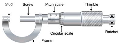
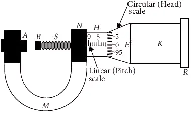
The screw gauge is an instrument used for measuring accurately the diameter of a thin wire or the thickness of a sheet of metal. It was invented by William Gascoigne. It consists of a U-shaped frame fitted with a screwed spindle which is attached to a thimble. A screw gauge is as shown in figure 1.

Pitch of the screw
It is defined as the linear distance moved by the screw forward or backward when one complete rotation is given to the circular cap.

Least Count of the Screw Gauge
The Least count (LC) is the distance moved by the tip of the screw, when the screw is turned through 1 division of the head scale.

Reading of a Screw Gauge

Consider figure 2. Place a wire between A and B, the edge of the cap lies ahead of Nth division of linear scale. Then
Linear scale reading (LSR) = N
If nth division of circular scale lies over reference line, then
Circular scale reading (CSR) = n × (LC)
Total reading (or observed reading) = LSR + CSR = N + n × (LC)
Zero error
When the two studs A and B of the screw gauge are brought in contact and if the zero of the circular scale does not coincide with the reference line then the screw gauge has an error. This error is called zero error.
1. Positive zero error
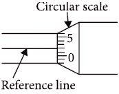
Zero error is said to be positive if the zero of the circular scale lies below the reference line as shown in figure 3.
Here , zero error = + (n × LC)
Here, n= division number on circular scale coincide with reference line.
zero correction (C) = negative of zero error
C = – zero error = – (n × LC)
Therefore, True reading = observed reading + zero correction = observed reading – (n × LC)

According to above figure,
n = 2
zero error = + (n × LC) = + (2 × LC)
2. Negative zero error
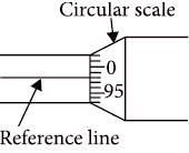
Zero error is said to be negative if the zero of the circular scale lies above the reference line as shown in figure 4.
Here, zero error = – (n × LC)
where, n= (Total number of divisions on circular scale) – (Division number coinciding with reference line).
zero correction (C) = negative of zero error
C = – zero error = – ( – (n × LC)) = n × LC
Therefore, True reading = observed reading + zero correction = observed reading + (n × LC)

According to above figure,
n = 100 – 98 = 2
zero error = – (n × LC) = – (2 × LC)
Read More: Electrical Engineering Interview Questions
Exercise
Q. A screw gauge gives the following reading when used to measure the diameter of a wire.
Main scale reading : 0 mm
Circular scale reading: 52 division
Given that 1 mm on the main scale corresponds to 100 divisions of the circular scale. The diameter of the wire from the above data is
- 0.52 cm
- 0.052 cm
- 0.026 cm
- 0.005 cm
Answer.
Least count of screw gauge =1/100 mm = 0.01 mm
Diameter = Divisions on circular scale × least count + main scale reading = 52 × 0.01 + 0
= 0.52 mm
Diameter = 0.052 cm
So, option (b) is correct.
Q. The pitch of the screw gauge is 0.5 mm and there are 100 divisions on its circular scale. The instruments reads +2 divisions when nothing is put in-between its jaws. In measuring the diameter of a wire, there are 8 divisions on the main scale and 83rd division coincides with the reference line. Then the diameter of wire is
- 4.05 mm
- 4.405 mm
- 3.05 mm
- 1.25 mm
Answer. Pitch = 0.5 mm
Total divisions on circular scale = 100
Least count (LC) = (Pitch/Total divisions on circular scale) = 0.5/100 = 0.005 mm
main scale reading = divisions x pitch = 8 x 0.5 mm
Observed reading = M.S.R. + C.S.R. = 8 x 0.5 + 83 x 0.005 = 4.415 mm
zero error = 2 x LC = 2 x 0.005 = 0.01 mm
zero correction = −(zero error) = − 0.01 mm
True reading of diameter = Observed reading + zero correction = 4.415 − 0.01 = 4.405 mm
So option (b) is correct.
Q. The pitch of a screw gauge having 50 divisions on its circular scale is 1 mm. When the two jaws of the screw gauge are in contact with each other, the zero of the circular scale lies 6 division below the line of graduation. When a wire is placed between the jaws, 3 linear scale divisions are clearly visible while 31st division on the circular scale coincide with the reference line. The diameter of the wire is
- 3.62 mm
- 3.50 mm
- 3.5 mm
- 3.74 mm
Answer.
Pitch = 1 mm
Total divisions on circular scale = 50
Least count (LC) = (Pitch/Total divisions on circular scale) = 1/50 = 0.02 mm
main scale reading = divisions x pitch = 3 x 1 mm
Observed reading = M.S.R. + C.S.R. = 3 x 1 + 31 x 0.02 = 3.62 mm
zero error = − 6 x LC = − 6 x 0.02 = −0.12 mm
zero correction = −(zero error) = − (−0.12) = 0.12 mm
True reading of diameter = Observed reading + zero correction = 3.62 + 0.12 = 3.74 mm
So option (d) is correct.
