An Adder is a digital logic circuit in electronics that performs the operation of additions of two number. Adders are classified into two types: half adder and full adder. The full adder (FA) circuit has three inputs: A, B and Cin, which add three input binary digits and generate two binary outputs i.e. carry and sum.
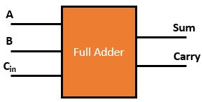
Let’s see an addition of single bits.
0+0+0 = 0
0+0+1 = 1
0+1+0 = 1
0+1+1 = 10
1+0+0 = 1
1+0+1 = 10
1+1+0 = 10
1+1+1 = 11
These are the least possible single-bit combinations. But the result for 1+1+1 is 11, the sum result must be re-written as a 2-bit output. Thus, the equations can be written as
0+0+0 = 00
0+0+1 = 01
0+1+0 = 01
0+1+1 = 10
1+0+0 = 01
1+0+1 = 10
1+1+0 = 10
1+1+1 = 11
The bold digit is the sum output. The output ‘1’of ‘10’ is carry output. ‘SUM’ is the normal output and ‘CARRY’ is the carry output.
Truth table of full adder
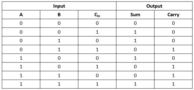
The truth table of the full Adder Circuit is shown in figure 2.
Implementation of half adder
Logical expression for Sum,

Logical expression for Carry,
![]()
Carry = AB + BCin + ACin
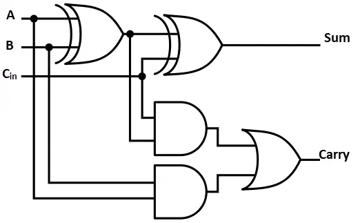
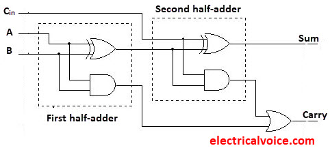
The FA works by combining the operations of basic logic gates, with the simplest form using two XOR, one OR & two AND gate.
Note:
1. Minimum number of NAND Gate required implementing FA = 9
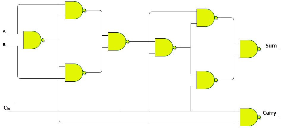
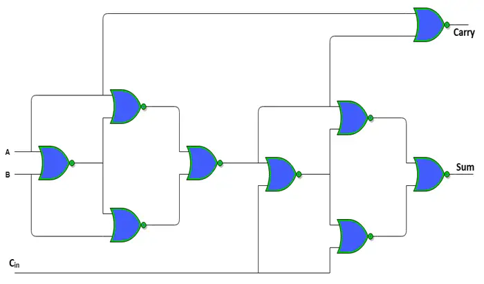
2. Minimum number of NOR Gate required implementing FA = 9
3. FA can be implemented by a combination of two half adder and one OR gate.
4. FA can be implemented by a combination of one 3×8 decoder and two OR gate.
Questions
Q.1 Which of the following circuits come under the class of combinational logic circuits?
- Full adder
- Full subtracter
- Half adder
- J-K flip-flop
- Counter
Select the correct answer from the codes given below:
- 1 only
- 3 and 4
- 4 and 5
- 1, 2, and 3
Ans. option d is correct
Q.2 A full adder can be made of
- two half adders
- two half adders and a NOR gate
- two half adders and an OR gate
- two half adders and a AND gate
Ans. option c is correct
