A subtractor is a digital logic circuit in electronics that performs the operation of subtraction of two number. Subtractors are classified into two types: half subtractor and full subtractor.
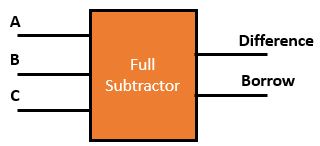
A full subtractor (FS) is a combinational circuit that performs a subtraction between two bits, taking into account borrow of the lower significant stage. This circuit has three inputs and two outputs. The three inputs are A, B and C, denote the minuend, subtrahend, and the previous borrow, respectively. The two outputs are the difference (A−B−C) and borrow.

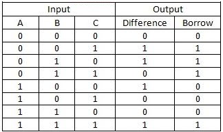
The truth table of the full subtractor Circuit is shown in figure 2.

Implementation of Full Subtractor
Logical expression for Difference,

Logical expression for borrow,


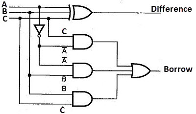
The FS works by combining the operations of basic logic gates, with the simplest form using one XOR, one OR, one NOT & three AND gate.
Note:
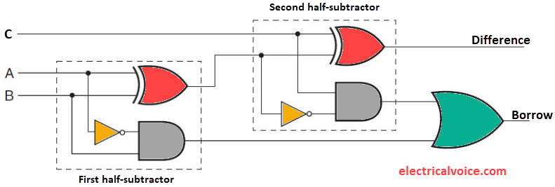
1. FS can be implemented with two half subtractor and one OR gate.

2. Minimum number of NAND Gate required implementing FS = 9
3. Minimum number of NOR Gate required implementing FS = 9
4. FS can be implemented by a combination of one 3×8 decoder and two OR gate.
