In case of block diagram reduction diagram, there is no standard procedure for reducing the block diagram to evaluate its transfer function. Also, the block diagram reduction technique is tedious and is difficult to choose the rules to be applied for reduction.
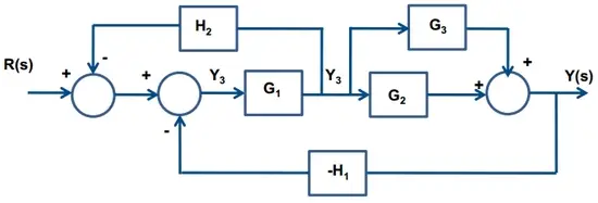
In order to avoid such problems, the block diagram is converted to signal flow graph and the formula is applied known as Mason’s gain formula to find the transfer function. Consider a block diagram as shown below.

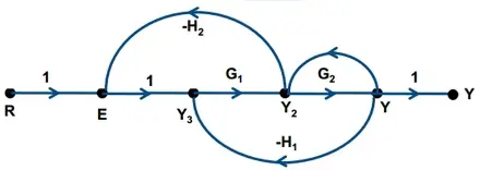
The signal flow graph of above block diagram is shown below.

1. Node: It represents the system variable which is equal to the sum of all incoming signals at the point. example, R, E, Y3, Y2, Y are all nodes.
2. Branch: The signal travels along a branch from one node to another in the direction indicated by the branch arrow.
3. Input node or source node
It is a node which has only outgoing branches. example, node R is the input node.
4. Output node or sink node
It is a node which has only incoming branches and no outgoing branches. example, node Y is the output node.
5. Path
A path is a traversal of connected branches in the direction of the branch arrows such that no node is traversed twice.
6. Forward path
The Path that connects the input node to output node is called forward path. example, 1-1-G1-G2-1.
7. Loop
The path such that which when traversed reach the node where initially started such that no node is traversed twice. example, 1-G1-(-H2).
8. Non-touching loops
Loops that do not have any branch or nodes in common.
Drawing and signal flow graph from block diagram
While drawing signal flow graph, in case, if there is any take-off point after a summing point then both of them are taken as one node in the signal flow graph. If the take-off point precedes the summing point then they are taken as the different point.
Mason’s gain formula
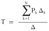
It is used for the determination of overall transfer function from the signal flow graph. The transfer function using Mason’s gain formula is given by

where
N = number of forward path
Pk = path gained of kth forward path
Δ = 1 − (sum of loop gain) + (sum of gain products of 2 non-touching loops) − (sum of gain products of 3 non-touching loops) + ………..
Δk = value of Δ for that part of signal flow graph not touching the kth forward path.
Excercise
Q. What is Signal Flow Graph?
Ans. A Signal Flow Graph is a diagram that represents a set of simultaneous linear algebraic equations. By taking Laplace transform the time domain differential equations governing a control system can be transferred to a set of algebraic equations in s-domain. The signal Flow graph of the system can be constructed using these equations.
Q. What are the basic properties of Signal Flow Graph?
Ans. The basic properties of the signal flow graph are:
- Signal Flow Graphs are applicable to linear systems.
- It consists of nodes and branches. A node is a point representing a variable or signal. A branch indicates the functional dependence of one signal on another.
- A node adds the signals of all incoming branches and transmits this sum to all outgoing branches.
- Signals travel along branches only in a marked direction and is multiplied by the gain of the branch.
- The algebraic equations must be in the form of cause and effect relationship.
