Schering bridge is an AC bridge which is used for the measurement of unknown capacitance. This is one of the most commonly used AC bridge. Schering bridge is shown in figure 1 under balance condition.
Introduction
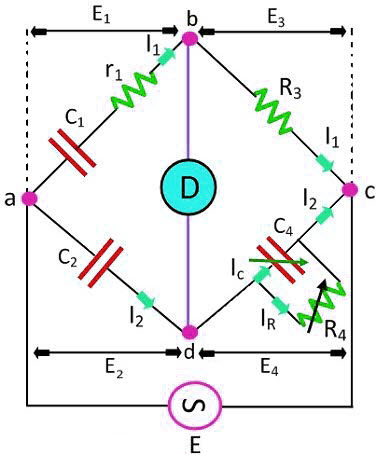
From figure 1, there are four arms as
arm 1 = ab
arm 2 = ad
arm 3 = bc
arm 4 = dc
where
C1 is an unknown value of capacitance to be measured.
r1 is a series resistance representing loss in C1.
C2 is a standard capacitor. It is an air or gas capacitor and hence loss-less capacitor.
R3 is a non–inductive resistance.
C4 is a variable capacitor.
R4 is a variable non-inductive resistance.
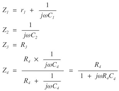
Therefore, the impedances of arms 1, 2, 3 and 4 are respectively,
At balance condition,
Z1Z4 = Z2Z3
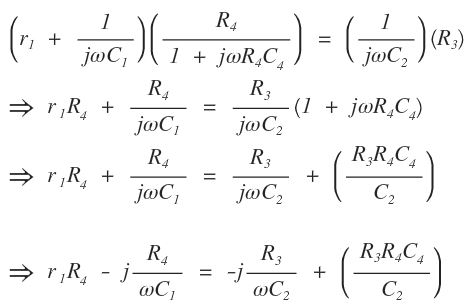
Equating real and imaginary parts on both sides,
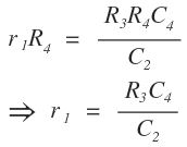
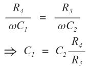
The independent variables in r1 and C1 are C4, R4 respectively. Therefore, Balancing is done by adjustment of R4, C4 with R3, C2 fixed.
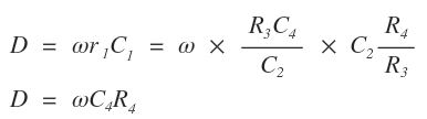
Dissipation factor (D) is given by
Advantages of Schering Bridge
1. The balanced equation obtained is independent of frequency terms.
2. By using fixed values of C2, R4, the dial of R3 may be calibrated to read the capacitance (C1) directly.
3. In case of fixed frequency, the dial of capacitor C4 can be calibrated to read dissipation factor directly as
D= ωC4R4.
Disadvantage
There is a difficulty in obtaining balance as R3 appears in both equations.
Application of Schering Bridge
This bridge is used for the measurement of the relative permittivity of dielectric materials.
