Maxwell inductance bridge is an AC bridge used for measurement of inductance of a coil by comparison with a variable standard self-inductance. Maxwell inductance bridge is shown in figure 1 under balance condition. Under balance condition, the current (Id) through the detector is zero. Hence current through arm ab and arm cd is the same. The current through arm ad and arm dc is the same.
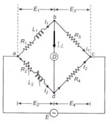
From figure 1, there are four arms as
arm 1 = ab
arm 2 = ad
arm 3 = bc
arm 4 = dc
where
L1 is an unknown self-inductance of resistance R1
R2 is a variable non-inductive resistance
L2 is a variable inductance
R3 is a fixed resistance
R4 is a fixed resistance
Therefore, the impedances of arms 1, 2, 3 and 4 are respectively,
Z1 =![]()
Z2 =![]()
Z3 = R3
Z4 = R4
At balance condition,
Z1Z4 = Z2Z3
![]()
![]()
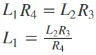
On comparing real and imaginary part both side, we have
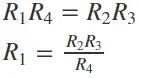
and
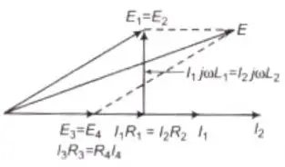
Phasor Diagram of Maxwell inductance Bridge
Advantages
1. The bridge balancing is simple.
2. These equations do not contain any frequency part.
3. This circuit is cheap.
