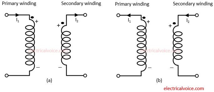
The Dot convention is a type of polarity marking for transformer windings which describes the phase relationships in the transformer schematic diagrams. In this, the dots are mentioned on the primary and secondary windings of the transformer. By convention, the dot represents the positive polarity. Before we learn dot convention in transformer, first see the two cases.
Case-1:
Consider two windings.

If both currents enter at both dots then we get an addition of magnetic flux and such type of coupling between two windings is known as positive coupling. See fig. 1(a).
OR
If both currents leave at both dots then we get an addition of magnetic flux and such type of coupling between two windings is known as positive coupling. See fig. 1(b).
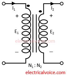
Case-2:
Consider two windings.
If one current enter at one dot and other current leaves at another dot then we get subtraction of magnetic flux and such type of coupling between two windings is known as negative coupling. See fig. 2(a) and fig. 2(b).
Note: Transformer is known as negative coupled device.
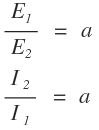
Dot Convention in transformer
Let us see different cases associated with the dot convention in transformer.
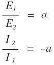
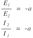
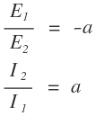
‘a‘ represents the turns ratio.

E1 and E2 represent primary and secondary winding induced voltages respectively. In the following examples, the polarity of secondary winding induced voltage (E2) is assumed randomly. This is how we will see several cases.
I1 and I2 represent primary and secondary winding currents respectively.
Case-1
Case-2:
Case-3:
Case-4:
Case-5:
Case-6
Note: In an ideal transformer while referring circuit from one side to another, always connect that part of the circuit having the same dot points.
Do practice by solving transformer MCQs.
