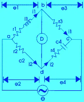
In the previous article, we have learned about Maxwell bridge. It is a modification of Maxwell’s bridge. The circuit diagram for Hay’s Bridge is shown below. It uses a resistance in series with a standard capacitor.

L1=unknown resistance having a resistance R1
R2, R3, R4=known non-inductive resistance
C4=standard capacitor
At balance,
e1e4 = e2e3

Separating real and imaginary term from above equation, we get

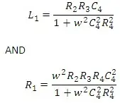
By solving the above two equations, we get

The Q factor of the coil is given by

Advantages
1) provides very simple expression for unknown inductance for high Q coils. This bridge is suitable for coils having Q > 10.
2) simple expression of Q factor.
3) From the expression of Q-factor, it is clear that for high Q factor the value of resistance R4 should be small.
Disadvantages
1) This bridge is suitable for measurement of high Q inductors.
