In control engineering, characterization of a controlled system is primarily determined by its dynamic behaviour which also characterizes the scope and the quality needed to solve a control task. The step response of the controlled system is used to reflect this dynamic behaviour.
A controller is one of the most important parts of the control system which measures the performance of the control system. Basically it is the mechanism which minimizes the difference between the system’s actual value (process variable) and its desired value (set point).
Outputs can be controlled to a particular value or the sequence of events can be performed or an event can also be performed by a control system if the specified conditions of inputs are satisfied. Complex mathematical functions or simple subtraction, addition for comparisons can also be performed by controllers.

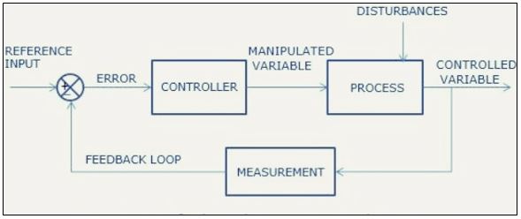
The difference between the set point (reference input) and the measured output gives out the parameter (error) mentioned in figure 1 which is applied to the controller. The controller then generates a control action to make the error zero. Control action which is generated manipulates the process variable closer to the reference input. There are sensor and transmitter in measurement systems. The process variable is measured by the sensor which produces electrical, mechanical or other related phenomena. The transmitter then converts that phenomenon into a signal which is suitable for transmission.
Importance of Controllers
1. Controllers help us to improve the steady-state accuracy by decreasing the steady-state error.
2. Controllers also improves stability.
3. Controller reduces the offsets generated by the system.
4. Controller controls the maximum overshoot of the system.
5. Controller reduces the noise signals generated by the system.
6. Controller increases the slow response of an overdamped system.
A controller shapes the error signal so that certain control criteria or specifications are met. These criteria may be the transient response characteristics, steady-state error, disturbance rejection, sensitivity to parameter change.
Types of Controllers
Three basic controller modes are Proportional controller, Integral controller, and Derivative controller. However, there are other controller modes which can be formed by the combination of basic controllers i.e. Proportional Integral (PI) Controller, Proportional Derivative (PD) Controller, and Proportional Integral Derivative (PID) Controller.
1. Proportional controllers
It is the simplest controller among the PID family. As the name suggests, the output (actuating signal) for the control action is directly proportional to the error signal. It repeats a measurement-computation-action procedure at every loop sample time ‘T’ like all automatic controllers.
In this, the output position is related to the deviation of the reference input point and measured control process variable. For a proportional controller, there are two conditions and these are written below:
1. The deviation between the input and output should not be large
2. There should not be a sudden deviation.
Figure 2 shows the block diagram of a system with a proportional controller. As the name suggests proportional controller output will be the error deviation multiplied an electronic circuit gain.

Mathematically,
![]()
or,
![]()
Using Laplace Transform, the gain of the proportional controller is
![]()
or

Hence, the transfer function of proportional derivative controller is KP.
Where,
U(s) = Laplace transform of the actuating signal u(t)
E(s) = Laplace transform of the error signal e(t)
KP = Proportional constant (Controller Gain)
KP should be kept greater than unity which will help in amplifying the error signal hence amplified error signal can be detected easily.
The transient response can also be changed by the proportional controller as per the requirement. It can also be used where the processing time of equipment or process is very large or where error magnitude is not needed to minimize to zero. The setting of a proportional constant can be represented as
a) Proportional Gain
b) Proportional Band
a) Proportional Gain: This concept is basically used in electronic controllers where the circuit gain acts as proportional constant. The proportional gain is defined as the percentage change in controller output to the percentage change in controller input.
![]()
The gain of the circuit can be controlled by changing the resistor value and hence the output of the system.
b) Proportional Band: Controller output band over which the final control element (e.g., a control valve) will move from one extreme to another. It is also known as throttling range or throttling band. It is defined as the percentage change in input controlled variable span which will cause a 100 % change in controller output.
Mathematically,
![]()
This concept is used in hydraulic controller and digital controller.
Relation between PB and Proportional Gain:

Offset error
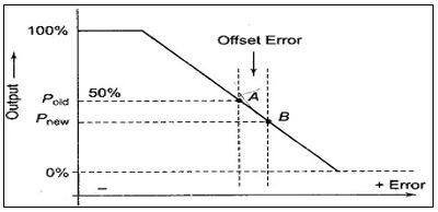
A proportional controller cannot eliminate the offset error, i.e. the difference between the desired value and the actual value as it requires an error to generate an output. If there is a disturbance in the controlled process value, any corrective control action, primarily based on Proportional Control mechanism will always give the error between the next steady-state and the desired value which results in a residual error called the offset error. Offset error is characterized by a permanent residual error in the operating point of the controlled variable when there is a change in load occurs. However, this offset can be reduced by selecting a higher value of controller gain (KP) corresponding to a narrow bandwidth. There will be an increase in the error as greater process demands put on the system or by increasing the reference points. Figure 3 shows the occurrence of offset error in a proportional control system. The system error is zero at nominal load with controller output P = 50%. A small difference between the percentage error values of points B and A is the offset error.

Advantages of Proportional Controller
a) Steady state error is reduced hence the system becomes more stable.
b) Easy to implement.
c) Slow response overdamped response is made faster.
d) Minimizes fluctuations.
e) Has high loop gain.
Disadvantages of Proportional Controller
a) No fine controlling.
b) Damping ratio is reduced which leads to increase in overshoot.
c) Presence of offset error.
d) Leads to the instability of the system for a very large gain.
e) Sluggish response for a wide proportional band.
Applications of Proportional Controller
a) For small set points or small load changes.
b) Can be used for temperature control of any material or any fluid.
c) Used for maintaining tighter tolerance and timely responsiveness.
2. Integral Controller
In the integral controller, controller output produces an output which is proportional to the integral of the error with respect to time. Control system with an integral controller is shown in figure 4.
Mathematically,
![]()
or,
![]()
Using Laplace transform,
![]()

Hence, transfer function of the controller is![]()
where, KI is the integral constant.

Advantages of Integral Controller
a) Decrease the steady-state error.
b) Because of their unique ability, these controllers can return the controlled variable back to the exact point, also known as reset controllers.
c) Responds to the continuous deviation.
d) Provides high output at the particular time after the error generated is for high value of KI.
Disadvantages of Integral Controller
a) These controllers are never used alone.
b) Unstable for an oscillatory response.
c) Introduces hunting in the system response about its steady-state condition.
d) Slow response time.
Applications of Integral Controller
Integral controllers are not used individually because integral controller alone will cause transient overshoot that produces saturation of the output (i.e. output cannot be operated beyond this limit).
3. Derivative Controller
It is also called as Rate action controller or anticipatory controller. As the name suggests, the derivative controller output is directly proportional to the derivative of the error signal. Control system with a derivative controller is shown in figure 5.

Mathematically,
![]()
or
![]()
Using Laplace transform,
![]()

Hence the transfer function of the derivative controller is KD.s
KD = Derivative constant
Advantages of Derivative Controller
a) Minimization of transportation lag effect which is due to the remote allocation of the sensor.
b) Minimization of peak error.
c) Can overcome overshooting and severe cycling.
d) Produces rapid response to counter the effect of rapidly changing errors.
e) Improves the transient response of the system.
Disadvantages of Derivative Controller
a) Amplifies the noise signal.
b) Does not eliminate the offset.
c) Ineffective for slowly varying error which causes drift.
Applications of Derivative Controller
The derivative controller produces no output when the error is constant so these controllers are not used alone.
4. Proportional integral (PI) Controller
The proportional-integral controller is one in which the actuating signal consists of a proportional error signal added to the integral of the signal. Control system with PI controller is shown in figure 6.

Mathematically,
![]()
Using laplace transform,
![]()
![]()
or
![]()
Hence, the transfer function of proportional derivative controller is ![]()
Advantages of Proportional Integral Controller
a) Good transient response.
b) Provides simplicity and directness.
c) Helps in stabilizing the controller gain.
d) Eliminates the offset error.
e) Provides better stability.
f) Improving the Gain Margin, Phase Margin.
Disadvantages of Proportional Integral Controller
a) System becomes sluggish due to the addition of integral term.
b) Takes larger time to stabilize the gain than the proportional controller.
c) Increases the order of the system by one which results in the reduction of stability of the system.
Applications of Proportional Integral Controller
a) For maintaining production rates in liquid flow control.
b) In steam pressure control.
c) Works as low pass filter.
d) Used for maintaining tighter tolerance and timely responsiveness.
5. Proportional Derivative (PD) Controller
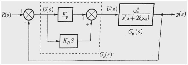
The proportional derivative controller produces an actuating error signal, which is the combination of the proportional error signal and derivative of the error signal. Control system with a proportional derivative controller is shown in figure 7.

Mathematically,
![]()
Using laplace transform,

or
![]()
Hence, the transfer function of proportional derivative controller is KP+KD s
Advantages of Proportional Derivative Controller
a) Improving the Gain Margin, Phase Margin, Peak overshoot.
b) Improves the stability of the system without affecting the steady-state error.
c) Can handle changes in fast load as the load change offset error is acceptable.
d) Reduces rise time, settling time.
Disadvantages of Proportional Derivative Controller
a) Cannot eliminate the offset error of proportional controller.
b) Damping ratio is increased.
c) Attenuates high-frequency noise.
Applications of Proportional Derivative Controller
a) Used in DC motor position control.
b) Used for tuning of fractional order controllers.
c) Works as high pass filter.
6. Proportional Integral Derivative (PID) Controller
The PID controller produces an actuating error signal, which is the combination of the proportional error signal, integral and derivative of an error signal. PID controller is shown in figure 8.

Mathematically,
![]()
Using Laplace transform,

Hence, the transfer function of PID controller is ![]()
Advantages of PID Controller
a) Improving the stability of the system.
b) Reduces the steady-state error.
c) Feasible and easy to implement.
d) Makes the system faster by reducing the time constant.
Disadvantages of PID Controller
a) Low robustness.
b) PID controllers are linear and symmetric so in nonlinear systems, the performance of controller varies.
c) Noise in derivative part.
Applications of PID Controller
a) Used for the regulation of pressure, speed, flow, temperature in the automatic control process.
b) Used in heat treatment of metals.
c ) Used in pH control neutralization.
d) Used in furnace temperature control.
Comparison of Controllers
| Parameter | Proportional | PI | PD | PID |
| Rise time | Decrease | increase | decrease | minor decrease |
| Settling time | small change | increase | decrease | minor decrease |
| Phase Margin | decrease | decrease | increase | increase |
| Offset | Present | zero | present | small |
| Overshoot | Increase | increase | decrease | minor decrease |
| Steady State Error | decrease | significant change | increase | no change |
| Stability | worse | worse | improve | better for small KD |
| System Filteration | linear network | Low pass filter (LPF) | High pass filter (HPF) | depends on use |
About Author
