A tunnel diode is a heavily doped p n junction diode with a special characteristic of negative resistance. Tunnel Diode was invented in 1957 by Leo Esaki. Hence, this diode is also called an Esaki diode. Leo Esaki noticed that if a semiconductor diode is highly doped with impurities, it (diode) will show negative resistance property. Negative resistance means when the voltage is increased, the current through it decreases.
In 1973, Leo Esaki received the Nobel Prize in physics for discovering the electron tunnelling effect used in tunnel diodes. The tunnel diode is usually made by forming a highly doped PN junction on a heavily doped N-type (or P-type) semiconductor wafer by a rapid alloying process. Tunnel diode is helpful when one requires fast switching speed i.e. fast response.
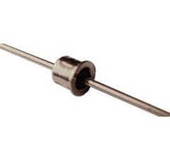
Tunnel diodes are usually fabricated from GaSb, gallium-arsenide(GaAs) and GeAs. It is highly doped having doping concentration 1:103. It has a narrower depletion layer due to high doping concentration. The operation of tunnel diode depends on the quantum mechanics principle known as “Tunneling effect“.
Tunnel diode Symbol & Equivalent Circuit
The Tunnel diode is a two-terminal device, one terminal is a cathode and another terminal is anode.
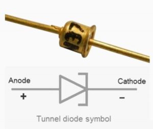
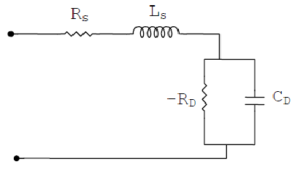
The equivalent circuit of a tunnel diode is shown in figure 3.
Tunnel diode Working
A normal p-n junction diode exhibits doping concentration of about 1 part in 108 (1 dopant atom in 108 Si or Ge atoms). If the doping level is further increased, say about 1 part in 103, we see the change in characteristics of the diode. As a result, the depletion layer gets very narrow. In comparison with the conventional diode, the depletion layer of the tunnel diode is 100 times narrower. The operation of the tunnel diode depends upon the tunnelling effect.
Let us gain more understanding with this in-depth analysis of tunnelling.
When the kinetic energy of a particle moving on one side of the barrier is less than the height of the barrier, it is impossible for the particle to pass through the barrier according to classical mechanics. Quantum mechanics proves that for microscopic particles, it still has a certain probability to pass through the potential barrier, which is also true in reality. This phenomenon is called the tunnelling effect. For harmonic oscillators, according to classical mechanics, the potential energy (PE) that is determined by the inter-nuclear distance can never surpass the total energy. Quantum mechanics proves that this inter-nuclear distance still has a certain probability. This phenomenon is also a tunnel effect.
Now, let’s have a clearer picture of how this tunnel diode works under different conditions.
Unbiased Condition
In an unbiased condition, no voltage will be applied to the tunnel diode. Since the state above the Fermi level is empty and the state below the Fermi level is filled with electrons, there is no tunnel current at this time. Only under the action of an applied voltage, the Fermi energy levels of the P and N regions move, and the carriers move to form a current.
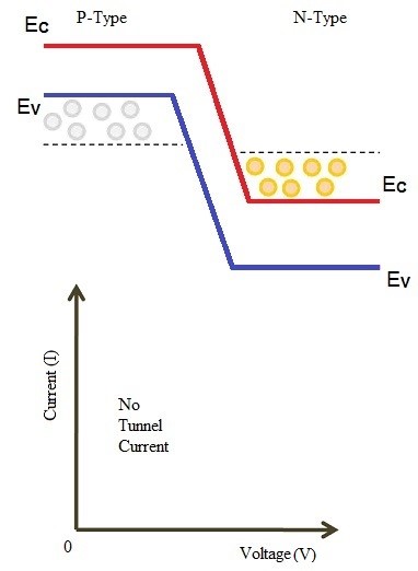
Small Forward Biasing Condition
When a small forward voltage is applied to the tunnel diode, which is less than the built-in potential of its narrow depletion layer, a very small amount of current start flowing which is due to few electrons starts tunnelling from conduction band of n region to valence band of p region.
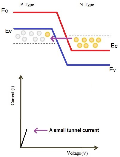
Increased Forward Bias
As the forward voltage is first increased, the diode current rises rapidly due to tunnelling effect. Electrons from the n region start tunnelling through the potential barrier to the p region. As the forward voltage increases, the diode current also increases until the peak point is reached.
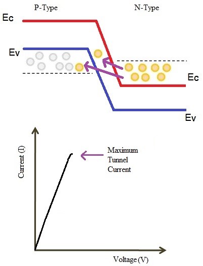
Further Increased forward Bias
As the forward voltage is further increased, the tunnelling effects get reduced and therefore flow of current across the diode also decreases. In this condition, the tunnel diode is said to be in the negative resistance region.
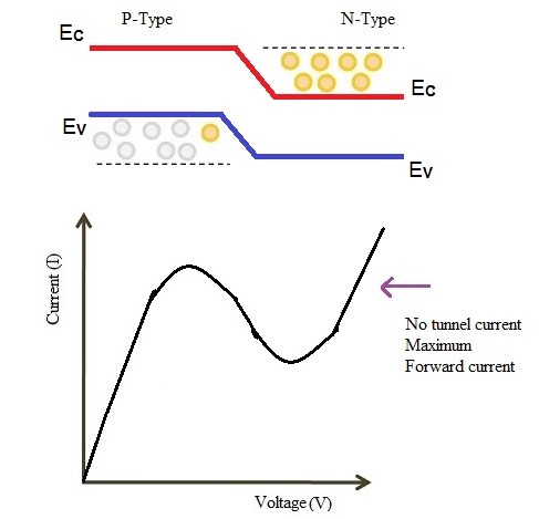
High forward bias condition
Under this condition, the tunnel diode behaves like a normal diode and the diode exhibits positive resistance once again. The valence band and the conduction band does not overlap at these voltage levels. This makes tunnel diode to operate in the same manner the PN junction diode works.
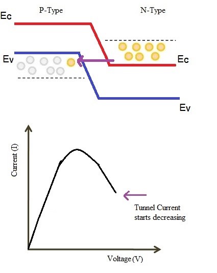
Tunnel diode Characteristics
Figure 5 shows the V-I characteristic of a tunnel diode.
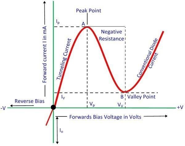
(i). As we can see in the plot shown, when the forward voltage across the tunnel diode increases from zero, the electrons from the n region “tunnel” through the barrier to the p region. As the forward voltage increases the diode current also increases until the peak point A. The diode current has now reached the peak current Ip (=2.2 mA) at about peak point voltage Vp (=0.07 V). Until now the diode exhibited positive resistance.
(ii). As the voltage is increased beyond Vp, the tunnelling action starts decreasing and the diode current decreases as the forward voltage is increased until valley point Vv is reached. In the region between peak point and valley point, the diode exhibits negative resistance.
(iii). When the forward bias is increased beyond the valley point Vv (=0.07 V) or point B, the tunnel diode behaves like a normal diode. In other words, from point B onwards, the diode current increases with the increase in forward voltage. This means, the diode once again reached the positive resistance.
Advantages of Tunnel Diodes
- It is a low noise device.
- It has a low cost.
- It has a very small size.
- It has a long life.
- Power dissipation is negligible.
- It is easier to fabricate.
- high-speed device
- low power device
- Insensitivity to nuclear radiations
- It can be used for many purposes like oscillator, Logic memory storage device, etc.
Disadvantages of Tunnel Diodes
- Being a two-terminal device, there is no isolation between the input and the output circuit.
- Voltage range over which it can be operated is 1 V or less.
Applications of Tunnel Diodes
- Due to its low power consumption, it is suitable for satellite microwave equipment.
- It can also be used in ultra-high-speed switching logic circuits, flip-flops, and storage circuits.
- Tunnel diodes can be used for microwave mixing and detection (in this case, doping should be appropriately reduced and made into reverse diodes), low noise amplification, oscillation, etc.
Author
Aniruddh Gupta
B.E. (Electronics & Communication)
IGEC Sagar, M.P., India
