In previous articles, we discussed different types of single-phase induction motors such as Split phase induction motor, Capacitor-start inductor motor, Capacitor-start capacitor-run induction motor, and Shaded pole induction motor. In this article, we will see another type of single phase motor i.e. Permanent Split Capacitor Induction Motor. It is also known as Permanent Split Capacitor Motor or single-value capacitor motor.
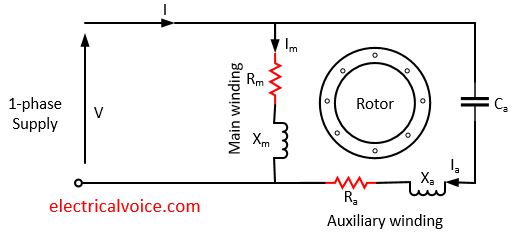
Like other single-phase motors, Permanent Split Capacitor Induction Motor is a single phase motor consists of a stator and a single-cage rotor. The stator has two windings i.e. main winding and an auxiliary winding. The auxiliary winding is also known as starting winding. In construction, these two windings are placed 90° apart in space. This motor has one capacitor i.e. Ca permanently connected in the auxiliary winding both at starting and running conditions. The paper spaced oil filled type capacitor is used in this motor. The Permanent Split Capacitor Induction Motor is shown in figure 1.

Unlike other single phase motors, auxiliary winding and capacitor are permanently connected to the motor. Also, centrifugal switch is absent in this motor.
Ca = capacitor
Rm = main winding resistance
Xm= main winding inductive reactance
Ra = series resistor connected in the auxiliary winding
Xa = auxiliary winding inductive reactance
Working of Permanent Split Capacitor Induction Motor
When the stator windings are energised from a 1-phase supply, the main winding carries current Im and the starting winding carries current Ia.
The capacitor Ca is connected in parallel during motor starting and running. The value of the capacitor Ca is chosen such that current Im is made to lag current Ia. Therefore, there is a time-phase difference (α) and 90° space difference between the two currents. These two currents produce a rotating magnetic field which starts the motor.
As the rotor speed increases, a counter E.M.F. is produced in the auxiliary winding that will limit the current through it to less than 1 Amp. when the motor reaches full speed. The small amount of current in the auxiliary winding when the motor is operating at full speed is small enough so that it won’t cause the start winding to overheat.
When the motor shaft sees an increase in its load, it will slow down slightly. The decrease in the rotor’s rpm causes a decrease in the counter E.M.F. which makes a larger potential difference between it and the applied voltage. The larger potential difference causes an increase in the current in the auxiliary winding, which will cause an increase in rotor torque that increases the rotor’s rpm. This characteristic allows the motor to operate with a constant speed under varying load conditions.
This motor produces a uniform torque. Due to this, noise is less during motor operation.
Advantages
- No centrifugal switch is required.
- As the capacitor is connected permanently to the circuit, the power factor is high.
- It has a higher pullout torque.
- Efficiency is high.
Limitations
- It has low starting torque, less than full load torque.
- The paper spaced oil filled type capacitor is used in this motor as the Electrolytic capacitor cannot be used for continuous running. The cost of the paper capacitor is higher, and size is also large as compared to the electrolytic capacitor of the same ratings.
Applications
- It is used by fans and blowers in heaters and air conditioners.
- It is used in refrigerator compressors.
- It is used in office machinery.
