Electrical Bus bar is an important component in the installation of an electrical distribution system. It is used for collecting current from incoming terminals of a power system and distributing it to various outgoing terminals. It acts as a junction between incoming power and outgoing power. Before going into deep in concept, let us first understand why we need a bus bar in the electrical bus bar system.
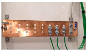
Why bus bar?
In an electrical connection when we connect more than two wires to the single wire as shown in figure 2, in that connection electrical end connection are exposed. Because of these open joint connection, the heat produced in wires may damage the insulation of the wire. If joints are not proper, there may be chances of an open circuit which is too risky. In order to avoid such condition and connect multiple wires in a proper manner, we use the electrical bus bar in the electrical distribution system.
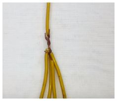
What is a bus bar?
Electrical Bus bar or simply Bus bar is “solid rectangular strip or bars which is used for collecting electric current from incoming terminals and to distribute them among outgoing terminals of the system”. It is also defined as “junction between the incoming source and outgoing terminals of the system”.
The shape of strip or bar may be other than rectangular size like round tubes, round bars or of square shape. In General, aluminium or copper material is used for the bar or strips. Aluminium is used over copper because of numerous advantages like low cost, corrosion resistivity, etc. Copper strips or bars are used where the high magnitude of the current is flowing through conductors.
The electrical bus bar sizes generally used in the system are 40×4 mm (160 mm2); 40×5 mm (200 mm2); 50×6 mm (300mm2); 60×8 mm (480 mm2); 80×8 mm (640 mm2) and 100×10 mm (1000 mm2). There are many types of electrical bus bar according to the applications. There are some points to be considered while selecting an electrical bus bar type such as
- Simple design as per requirement.
- There should be provision for maintenance without interrupting the power supply.
- If the load on system increase then there should be scope for extension.
- Installation should be cheap.
Types of Electrical Bus bar System
Let us discuss the various types of electrical bus bar system.
1. Single Bus-Bar Arrangement
Single Bus-Bar Arrangement is the basic and easiest design consisting of a single group of bus-bars or strips. This set of bus-bars connects all the components present in the system such as generators, transformers and feeders, etc. The circuit breakers keep eye on each generator and feeder. The isolators are used for isolation of generators, feeders and circuit breakers from the busbars when we keep out it for maintenance.
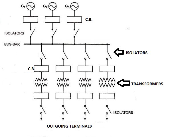
Advantages of Single Bus Bar Arrangement
- Low initial cost.
- Simple and easy to operate.
- The maintenance requirement is low.
Disadvantages of Single Bus Bar Arrangement
If a fault occurs on a bus bar the whole system gets affected. While in case of maintenance of the busbar, supply gets interrupted. This design is not flexible for a large power system.
2. Single Bus Bar Arrangement with Bus Sectionalizing
Name itself explain that bus-bar is sectionalized by a circuit breaker and isolating switches. This arrangement does not lead complete blackout if a fault occurs on any system. This method of sectionalizing the bus bar is used in large generating stations, where several units are installed. In General, 2 to 3 sections of the electrical bus bar are used. Actual Single Bus-Bar Arrangement with Bus sectionalization is shown below.
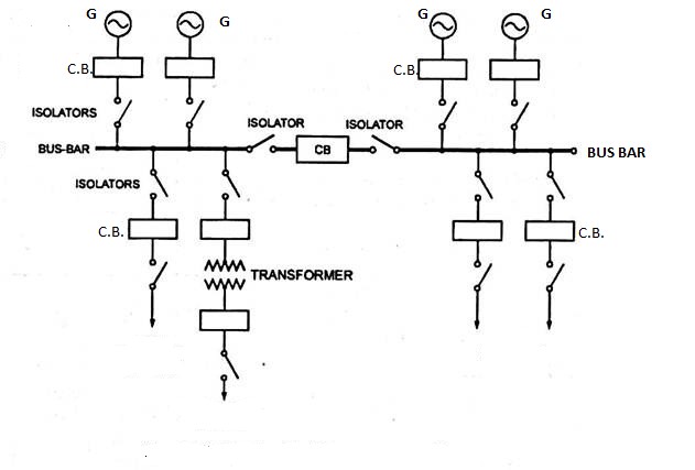
Advantages
- If a fault occurs on any section of the bus bar, it can be isolated by isolators without affecting the existing system and other sections.
- one section can be completely shut-down for maintenance and repairs without affecting the supply of the other section.
- By adding a current limiting reactor between section, the fault level can be reduced thereby circuit breakers of lower capacity can be used.
3. Main and Transfer Bus Arrangement
Main and Transfer Bus Arrangement have two buses namely main bus and transfer bus or auxiliary bus bar. This kind of arrangement is suitable for a system where the power system is interconnected with so many connections and flexibility are a very important issue. This arrangement has flexibility, continuity of supply and we can allow maintenance after some interval of time without total blackout. This combination of main and transfer bus has been used where we need the loads and continuity of supply.
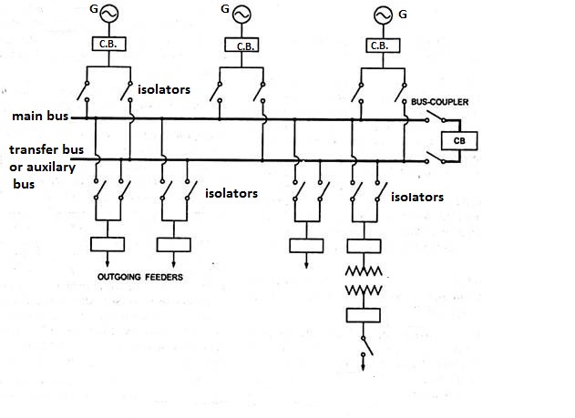
The figure 5 shows the pictorial view of the main and transfer bus bar system. According to figure 5, each generator and feeder is connected to either bus-bar with the help of bus coupler. For normal working condition, the main bus bar is in operation while maintenance of the main bus bar, the transfer bus bar is in operation. In this arrangement, a bus coupler is usually used so that change the connection from one busbar to the other busbar.
Advantages of Main and transfer busbar system
- If a fault occurs on any one bus then we can transfer the load to other bus bars without disturbing the continuity of supply.
- Maintenance of other components like feeder circuit breakers can be carried by putting them on an additional bus and keeping the main bus in operation.
- Substation maintenance is cheaper.
- The bus potential can be used for relays.
- Maintenance of the main bus can be carried by transferring the entire load on the auxiliary bus bar.
Disadvantages of Main and transfer busbar system
- As additional bus added to the system then the overall cost of system increases.
- After transferring all circuits from the main bus to auxiliary bus if a fault occurs on any circuit in load may cause a complete shutdown.
4. Double Bus Double Breaker Arrangement
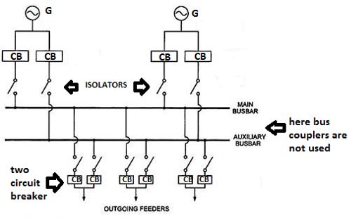
This system is quite similar to the previous one but the only difference is that every circuit is provided with two circuit breakers and bus couplers are not used. It fulfills the deficiency of previous electrical bus bar system. We can transfer the load from one bus to the other whenever desired, without interruption. This arrangement provides the advantage of maximum flexibility and reliability because the interruption of supply due to the faults and maintenance is minimum. A circuit breaker can be taken out for maintenance and repair. The load can be shifted on the other circuit breaker easily. This system has a disadvantage of very high operational cost and maintenance cost.
5. Sectionalized Double Bus Arrangement
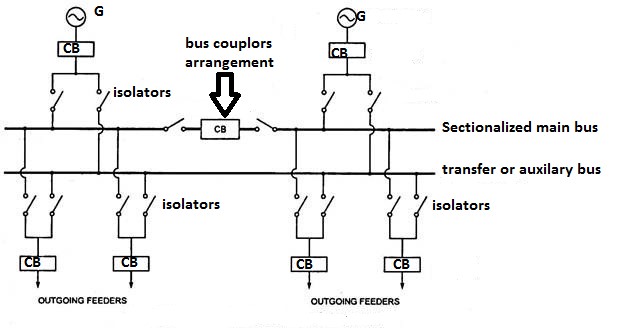
In this arrangement, the main bus bar is sectionalized into two bus bars in which one of them is duplicate bus bars and the other is the main bus bar. These two bus bars separated by bus coupler arrangement. Since only one circuit breaker is used for one circuit, the cost of a system decreases comparatively. In this arrangement, any section of the bus bar can be isolated for maintenance while any section may be synchronized with any other through the auxiliary bus bar. Here only the main busbar is sectionalized while transfer bus bar is used as it is.
6. One-and-a-Half Breaker Arrangement
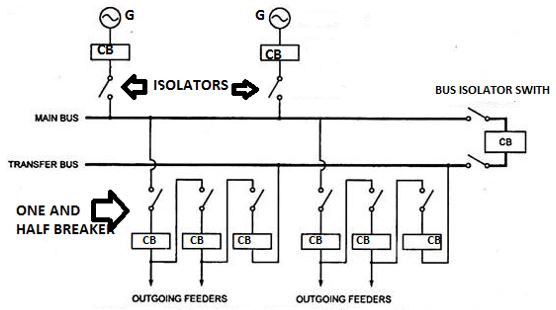
The name itself indicates that one and a half circuit breaker is used for one circuit. It means two circuit breakers are used for three circuits. This arrangement fulfills all deficiency in double bus double breaker arrangement and it affects saving in the number of circuit breakers. This arrangement is used in an important large interconnected power system where power handled per circuit is large. This arrangement has been used in Modern EHV (400 kV) and UHV (750 kV) substations.
Advantages
- This arrangement provides guaranteed continuity of supply as a fault in a bus or in a breaker will not interrupt the supply.
- There is scope for expansion of circuits to the system.
- The bus potential can be used as a supply to relays.
Disadvantages
- When a fault occurs on the system, two breakers are to be opened which leads to complication in relaying system.
- High maintenance cost.
- In case of maintenance of breakers, we have to go for load shedding. If we don’t go for load shedding then two breakers are open and other circuit works with only one breaker.
7. Ring Main Arrangement
In ring main system, two bus bars are coupled with the help of bus coupler and one of them is sectionalized to form ring-type structure. Each feeder is supplied from two sides so if anyone side failed to supply, the other side supply maintains continuity of supply. Hence high flexibility of the system is achieved. Again, if any system gets failed then there is an option for maintaining supply continuity. The effect of fault in one section is limited to that section only, the rest of the sections continue to operate normally. As we can see in the diagram that circuit breakers used are same in number like the single bus bar system hence this arrangement is cheaper as compared to other arrangements. We can take circuit breakers for maintenance and repair without interrupting the supply.
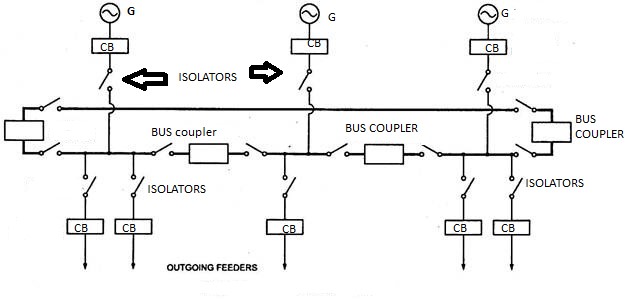
Drawbacks
The drawbacks of this system are:
- It is very difficult if we want to expand the system.
- If any section gets open for any reason, there may be a possibility of overloading of the existing system since load gets distributed to the remaining system.
8. Mesh Arrangement
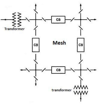
Name itself indicates that arrangement looks like mesh. The circuit components installed in buses are in such fashion that it forms a mesh. It is again an economical arrangement since fewer circuit breakers are required. It needs fewer circuit breakers than that are required by other arrangements. It is used for substations where a large number of circuits are interconnected. As we can see in the arrangement (Figure 10) that eight circuits are controlled by four circuit breakers. If a fault occurs on any section, two circuit breakers have to open, which results in the opening of the mesh. This arrangement provides security against busbar faults but lacks switching facility.
Applications of Electrical Bus bar
1. Mainly it is used in electrical system connection like Power stations, housing, hospitals, buildings etc.
2. An electrical bus bar is used in a hybrid vehicle where we need to connect batteries in parallel.
3. It is also used to connect power Electronics component together.
4. Bus bar made of a capacitor is used in motor drive.
5. It is also used in traction drives for connecting drive terminals.
6. It is also used in aerospace power distribution.
7. An electrical bus bar is used in a motor armature bus bar.
8. It is also used in computer power distribution.
Author
Sarang Adsad
B.Tech. (Electrical Engineering)
Shri Sant Gajanan Maharaj College of Engineering, Shegaon.

good notes
I want this material
Very informative explanation with schematic diagram! May I have this soft file? My email: oemchhun070@gmail.com
Good Notes. Thanks for Sharing