The open circuit test is performed on a transformer to find no-load (or shunt branch) parameters and core loss (or iron loss). This test is also known as the no-load test. This test is always preferred to perform on the low voltage (LV) side of the transformer. This test is always performed on the rated voltage at the input side of the transformer.
By doing this test, we are going to find
(i) Shunt branch parameters like
- No-load current (Io)
- Core loss resistance (Rc)
- Magnetizing reactance (Xm)
- Core loss current (Ic)
- Magnetizing current (Im)
(ii) No-load power (Wo) or core loss or iron loss
The connection diagram of open circuit test on transformer is shown in figure 1. This test is performed at the low voltage (LV) side. The high voltage (HV) side is open-circuited.
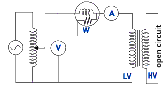
While performing open circuit test on transformer, the voltmeter reads rated applied voltage (Vo), the ammeter reads no-load current (Io, is very less value i.e. 2 to 5 % of full load current), and the wattmeter reads no-load power (Wo).
Why open circuit test is done on LV side of transformer?
The open circuit test is done on LV side of the transformer due to instruments (ammeter and voltmeter) constraints.
If we place the voltmeter at the high voltage (HV) side, it has to measure high voltage. The voltmeter with high ranges is not readily available. Also, a source of rated voltage is required. The source of such voltage is also not easily available.
On the other hand, if we place the voltmeter at the low voltage (LV) side, it has to measure low voltage. The instruments (such as ammeter, and voltmeter) with lower ranges are readily available.
The ammeter can measure no-load current more accurately at the LV side as compared to the HV side. As we know that, the no-load current is only 2 to 5 % of the full load current. If we place the ammeter at the HV side, it has to measure the referred value of the no-load current. This referred value is even smaller than the value on the LV side. So we have to use a more accurate ammeter on the HV side. Such an accurate ammeter is not readily available.
These are the reasons why open circuit test is done on LV side of transformer.
Note: It does not mean that we cannot do the open circuit test on the HV side of the transformer but we prefer the LV side due to ammeter and voltmeter constraints as discussed above.
Note: The reading of the wattmeter or core loss will never change whether we perform an open circuit test on the LV side or HV side.
Figure 2(a) shows the equivalent circuit when open circuit test on transformer is performed. As we know that the no-load current is very small i.e. 2 to 5 % of the full load current. Hence the voltage drop in the LV winding can be neglected. Hence equivalent circuit becomes as shown in figure 2(b).
The wattmeter reading (Wo) gives the core loss or iron loss. Hence it is given by
$\\W_{o}=V_{o}I_{o}\cos \phi _{o}=Core\; loss\\\\ \cos \phi _{o}=\frac{W_{o}}{V_{o}I_{o}}\\\\ \phi _{o}=\cos^{-1}\left ( \frac{W_{o}}{V_{o}I_{o}} \right )$
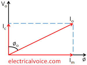
From phasor diagram, we can see that
$\\I_{c}=I_{o}\cos \phi _{o}\\ I_{m}=I_{o}\sin \phi _{o}\\\\ \Rightarrow I_{o}=\sqrt{I_{c}^{2}+I_{m}^{2}}$
$\\ \Rightarrow R_{c}=\frac{V_{o}}{I_{c}}\\\\ \Rightarrow X_{m}=\frac{V_{o}}{I_{m}}$
Core loss can also be written as
$Core\; loss=W_{o}=I_{c}^{2}R_{c}$
Note: Under the no-load condition, the power factor is very poor because the value of Io is very less and the Φo value is very large. Hence cosΦo is a very low value.
Note: If the drop across LV winding is not neglected then the wattmeter reading is
$W_{o}=Core\; loss+I_{o}^{2}R_{1}$
