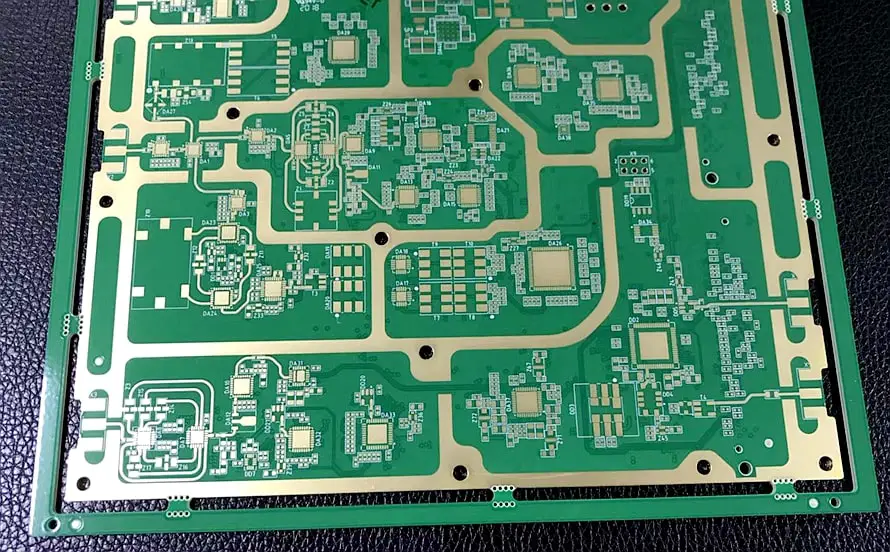
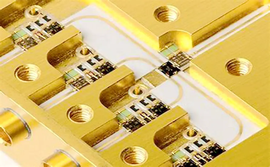
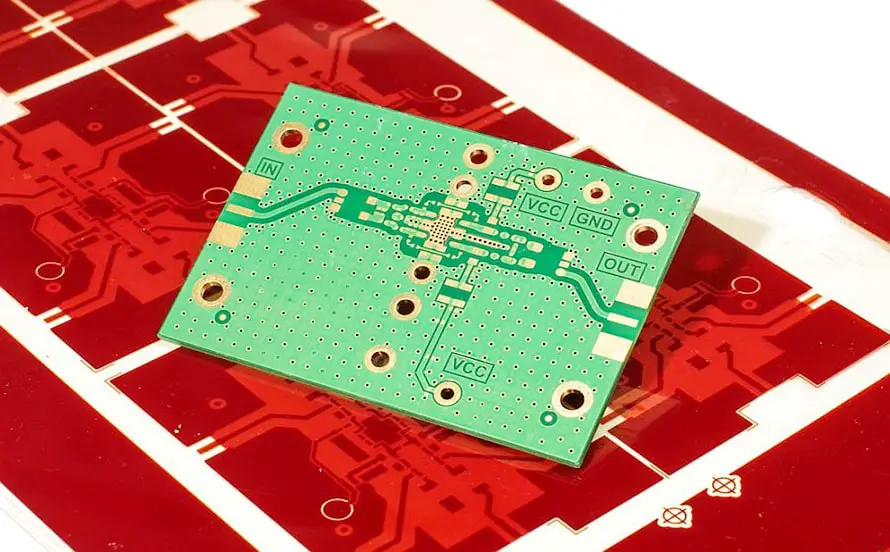
Microwave PCBs are applied in most of the electronics used today. These include radar systems, telecommunication, and even medical equipment. These include the transmission of microwave signals. Proper signals should be designed and installed with appropriate materials that do not affect the signals and their performances.
The article will highlight the manufacturing issues in microwave PCBs. Then, the probable solutions for it will also be discussed.

What Materials Are Used in Microwave PCB?
The airflow and heat sinking on Microwave PCBs require specific materials to obtain high-frequency signals. PTFE (polytetrafluoroethylene), Rogers, and ceramic are typical materials used to create such structures.
Polytetrafluoroethylene
PTFE has a very low dielectric constant and a low loss tangent, making it suitable for frequency circuits. This insulating material also has desirable signal characteristics, such as a low signal loss, which is improper in microwave devices.
Rogers Materials
Rogers materials like RO4000 and RO3000 are common for Microwave PCBs. They are good from dielectric constants’ point of view since they possess fairly good thermal stability and mechanical properties. These materials have been developed to meet highly frequent signals and are quite effective in their function.
Ceramic Substrates
Alumina and aluminum nitrate are examples of ceramic substrates. These materials have high thermal conductivity and low dielectric loss. This allows them to be used in advanced and high-power applications. Ceramic materials also have high mechanics, strength, and durability.
Properties of Common Microwave PCB Materials
| Material | Dielectric Constant (Dk) | Loss Tangent (Df) | Thermal Stability |
| PTFE | 2.1 | 0.001 | High |
| Rogers | 3.5 | 0.002 | Very High |
| Ceramic | 9.8 | 0.0005 | Extremely High |
The choice of the material to be incorporated depends on the characteristics of the application, such as the operating frequency, thermal conductivity, and mechanical properties, among others. The characteristics of each material used must be understood and considered to achieve reliability in Microwave PCBs.
Understanding Microwave PCB
Microwave PCBs are a unique type of printed circuit board suitable for microwave signal frequency, from 300 MHz to 300 GHz. Most high-frequency PCBs are because accurate signal transfer is required for telecommunication, satellite communication, radar systems, and medical equipment applications.
One must design a material with unique properties and choose appropriate materials for these applications.
Some of the major characteristics of Microwave PCBs are high SI, low losses dielectric, and good thermal conductivity. Such boards employ Dielectric constants (Dk) and loss tangents (Df) and are made from PTFE (Polytetrafluoroethylene), Rogers, and Ceramic substrates.
These materials are useful for reducing signal loss and guaranteeing high-frequency stability. However, equal precautions must be taken to control the levels of impedance and layout and the distances between the two.
Comparison of Microwave PCB with Standard PCB
| Feature | Microwave PCB | Standard PCB |
| Frequency Range | High (300 MHz – 300 GHz) | Low (up to several MHz) |
| Material | PTFE, Rogers, Ceramic | FR4 |
| Signal Integrity | Critical | Moderate |
| Dielectric Loss | Low | Higher |
| Thermal Stability | High | Lower |
Conceive these distinctions while developing Microwave PCBs to suit the high-frequency circulation in the board.

Design Considerations
When designing Microwave PCBs, special attention should be paid to the layout and details between the layers to provide signal strength. Proper layout helps achieve less loss and interference between signals and keeps adequate spaces between the components and traces. This spacing must be done, particularly where the operating frequency is high, so any changes may have significant effects.
Another important factor is impedance control. Impedance must be continuously maintained along the PCB to guarantee signals’ transmission without much reflection or distortion. The features that must be carefully controlled are the traces’ width and spacing and the material’s choice, for which dielectric properties must be known.
Thermal management is important because microwave power levels can be quite high. Specific ideas for improving thermal conductivity include using components with high thermal conductivity, utilizing thermal vias, and designing layouts for thermal management.
These are crucial design factors in realizing the performance and reliability needed in Microwave PCBs.
Manufacturing Challenges
High-Frequency Signal Integrity Issues
One of the interesting topics in microwave PCB manufacturing is signal integrity at high frequencies. High-frequency signals can be easily dropped, reflected, and interfered with, so transmitting signals with high frequencies is not very easy. When designing and manufacturing a PCB, its characteristics should strictly correspond to the operating frequency, layout, materials, and components, eliminating signal degradation.
It depends on the dimensions of manufacturing since any unevenness of the trace width, the spaces between the traces, or differences in the material type used affect the signal and ultimately lower the capacity of the device.
Material Handling Difficulties
Microwave PCBs are made from various materials, including PTFE, Rogers, and ceramics. These materials have several characteristics that make handling them, especially when manufacturing, a little challenging. For example, PTFE is rather flexible, and the material can be easily torn, laminated, and drilled. However, it is not too easy to do.
Nonetheless, as this is gaining popularity and looks like a promising method of creating new materials, it is crucial to know that the mechanical characteristics of Rogers materials are incomparable with other materials and need to be strictly regulated by temperature and pressure. Ceramics are also brittle because they are prone to breaking and fracturing under pressure. Thus, they easily get damaged, and stoneware and earthenware need certain apparatus.
Precision and Accuracy in Manufacturing
Microwave PCBs are used for manufacturing and require very fine and accurate layouts. Since the applications are frequent, even a minor change in the dimension of the PCB could result in major issues.
Applications such as laser drilling and precise chemical etching are typically used to achieve the required accuracy. The above-stated processes must be done effectively to obtain good and reliable PCBs.
Quality Control Challenges
Another vital process in Microwave PCB fabrication is quality control. Hence, due to the performance demands, thorough testing and inspection are required for every manufacturing process step. This entails ascertaining whether or not there are defects in the materials to be used, ensuring that the trace dimensions are accurate, and finally, proving that the signal is complete.
Equipment such as network analyzers and time-domain reflectometers is frequently necessary to measure high-frequency characteristics. Effective quality assurance measures enable one to prevent insignificant problems from escalating to big catastrophes, expending a lot of time and money on rectification.
Addressing these manufacturing challenges is essential for producing high-quality Microwave PCBs that meet the demands of modern high-frequency applications.

Solutions and Tips
Here are some solutions and tips.
Best Practices for Material Handling
Specialized materials used in Microwave PCBs like PTFE, Rogers, ceramics, and others must be handled carefully to avoid harm. For PTFE, many precautions need to be taken, which include minimizing the chances of contamination as much as possible. This is because laminating can lead to deformation if the appropriate drilling methods, such as low-stress ones, are not used.
When processing Rogers materials, make sure they are correctly subjected to accurate temperature and pressure so it will not affect the properties that they possess. Ceramics need to be handled carefully to avoid breaking.
Techniques for Maintaining Signal Integrity
Preserving signal integrity in high-frequency PCBs requires proper designs and techniques during manufacturing. Signal losses should, therefore, be kept to the minimum by using high-quality, low-loss materials.
Therefore, accuracy can be maintained by controlling signal impedance via appropriate trace width and distance construction.
Therefore, ground planes and shielding should be used to solve the problem of electromagnetic interference. Vias and interconnects should be designed and placed correctly so as not to cause signal reflection or loss. Continuous design implementation and prototyping can be done via top-of-the-line software that identifies possible problems in the design.
Advanced Manufacturing Technologies
Laser drilling or precision etching are some of the technologies used to produce Microwave PCBs due to their accuracy. Laser drilling techniques offer a precise and accurate technique, for via formation and micro via formation, which is offered by laser drilling techniques to reduce the possibility of mis-drilling and misshaping the holes.
High-frequency and high-speed signals require the regulation of the traces and other features, which is possible through precision etching. Modern designs also incorporate these technologies, creating a more precise and accurate manufacturing process that meets signal integrity and performance demands.
Quality Assurance Methods
It is crucial to use sound quality assurance procedures for Microwave PCBs. Test the process at different steps, such as during incoming material control, during the manufacturing process, and at the end. Use sophisticated instruments like network analyzers and time domain reflectometer equipment to assess signals and high-frequency signals.
This should be done with constant quality assurance and control and checking for any defects at the initial stage of production. Consistent checks on quality assurance procedures are important, with special consideration for technological and market changes.
If these solutions and tips are implemented, they could help manufacturers control the difficulties involved in Microwave PCB production and provide quality and dependable products for high-frequency applications.
Conclusion
Manufacturing Microwave PCBs entails overcoming technological barriers regarding signal integrity, material management, delicate measuring, and reproducibility. Employing the practices explained above, with technological innovations and quality assurance procedures, manufacturers can develop reliable boards with high-frequency capability, enhancing their quality.

2 thoughts on “Manufacturing Challenges and Solutions for Microwave PCB”