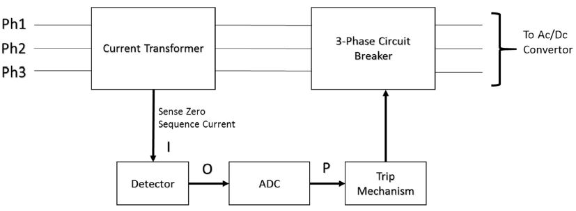
A ground fault circuit interrupter (GFCI) is a device that cuts off an electric power supply when it detects the ground fault in the system and hence prevents the system from severe damage. The GFCI monitors the current flowing into different phases and neutral. It turns off the power supply by sending a tripping signal to the circuit breaker if there is a negative sequence current flowing through the neutral. The GFCI shuts off the circuit in less than one-tenth of a second. The Block diagram of GFCI is shown in the figure as shown below.

Circuit
Basically, GFCI consist of five main components:
1. Current transformer (CT)
2. 3-phase circuit breaker
3. Detector
4. Amplifier
5. Trip mechanism
Working of Ground Fault Current Interrupter Protection Circuit
This Current transformer (CT) is a toroid differential sensing transformer that detects a current unbalance between the phase wires. A Detector senses the zero sequence current flowing through the neutral. Under normal conditions, no current flows through the neutral. During abnormal conditions, a zero sequence current flows through the neutral. The detector senses it and sends a signal to the trip mechanism after converting the signal into digital form. The trip mechanism contains an electronic relay that continuously compares the input with the prefixed reference value. When the input signal from Analog-to-digital (ADC) is greater than the reference value, the relay operates and sends a tripping signal to the circuit breaker.
The following table shows the different possibilities in a GFCI operation and their results.
| S.No. | I | O | P (Digital form) | Circuit Breaker Operation |
| 1. | I = 0 | 0 | 0 | Closed |
| 2. | I < Iref | I < Iref | 0 | Closed |
| 3. | I ≥ Iref | I ≥ Iref | 1 | Open |
