What is an analog-to-digital converter?
An analog-to-digital converter (ADC) is a system that converts an analog signal to a digital signal. For example, a sound picked up by a microphone into a digital signal.

The output of a microphone, the voltage at a photodiode or the signal of an accelerometer are the examples of the analog values that need to be converted so that a microprocessor can work with them.
Analog signals are directly measurable quantities. Digital signals only have two states i.e. 0 and 1.
Why is ADC needed?
- Microprocessors can only perform complex processing on digitized signals.
- When signals are in digital form they are less susceptible to the deleterious effects of additive noise as compared to analog signals.
- ADC Provides a link between the analog world of transducers and the digital world of signal processing and data handling.
What are the Applications of ADCs?
- ADCs are used virtually everywhere where an analog signal has to be processed, stored, or transported in digital form.
- Some examples of ADC usage are digital voltmeters, cell phone, thermocouples, and a digital oscilloscope.
- Microcontrollers commonly use 8, 10, 12, or 16-bit ADCs, our micro controller uses an 8 or 10 bit ADC.
Types of ADC
- Ramp type ADC
- Dual Slope type ADC
- Integrating type ADC
- Flash ADC
- Successive Approximation ADC
- Delta-Sigma ADC
1. Ramp type ADC


Working
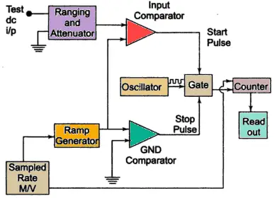
- The block diagram of ramp type ADC is shown in figure1.
- Initially, a ramp voltage is initiated as multivibrator sends a pulse to ramp generator. Also, the counter is reset to 0.
- Now, the ramp voltage is compared continuously with the input analog voltage using input comparator.
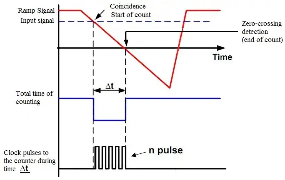
- Once ramp voltage becomes equal to the input voltage, the input comparator output becomes high and generated pulse opens the gate. The oscillator drives the counter.
- The ramp voltage is decreasing in value. The another ground comparator compares the ramp voltage.
- Once ramp voltage reaches zero voltage, the ground comparator generates a pulse that will close the gate and hence counter.
- The time duration of the gate opening is proportional to the input analog voltage.
- Therefore, the analog voltage is converted into time and the time counts represent the magnitude of the voltage(digital value).
- So, it is also called as voltage to time conversion.
Advantages
- It is easy to design.
- Low cost
- ADC output can be sent over long distances.
Disadvantages
- large errors possible due to noises.
- filters are required.
- excellant ramp linearity requirement.
2. Dual Slope type ADC

Working
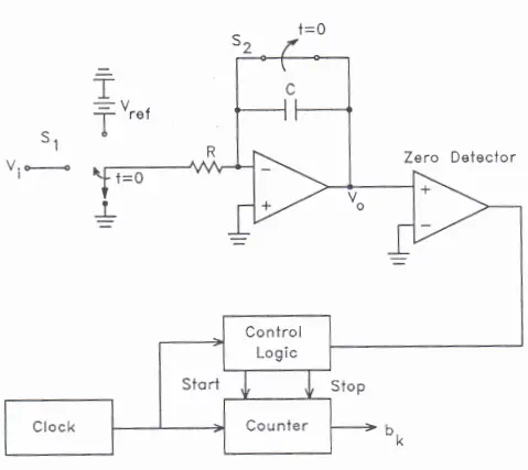
- At t<0, S1 is set to ground, S2 is closed, and counter=0.
- At t=0 a conversion begins and S2 is open, and S1 is set so the input to the integrator is Vin.
- S1 is held for TINT which is a constant predetermined time interval.
- When S1 is set the counter begins to count clock pulses, the counter resets to zero after TINT
- Vout of integrator at t=TINT is VinTINT/RC is linearly proportional to Vin
- At t=TINT S1 is set so -Vref is the input to the integrator which has the voltage VINTINT/RC stored in it.
- The integrator voltage then drops linearly with a slope -Vref/RC.
- A comparator is used to determine when the output voltage of the integrator crosses zero
- When it is zero the digitized output value is the state of the counter.
Advantages
- The conversion result is insensitive to errors in the component values.
- Fewer adverse effects from “noise”
- High Accuracy
Disadvantages
- Slow
- Accuracy is dependent on the use of precision external components
- Costly
5. Successive Approximation ADC

Principle of operation
It can be explained with the example of weight and a balance. Suppose that we have to determine the weight of an object with the help of a balance. An object is placed on one side of the balance and a weight is placed on another side.
If a weight placed is greater than object weight. The weight is removed and another weight of smaller value is placed. The measurement is performed. If the weight is less than the object, then a smaller weight is added to the weight already present. In this way, by adding and removing the weights, the object weight can be determined. Now, if the weight is greater than the object weight, then the added weight is removed and a smaller weight is added and measurement is done.
Successive Approximation Type ADC works on this principle.
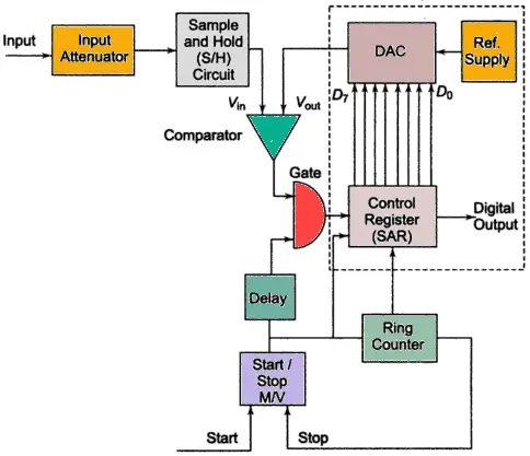
- Initially, a start pulse is given by start/stop multivibrator to the Control Register(SAR) through the gate. The SAR output is 00000000.
- The Vout is 0. The DAC output Vout is compared with the input voltage Vin using comparator.
- If Vin>Vout, the comparator output is positive. During first clock pulse, bit D7 is set to 1 and Vout becomes half reference voltage. The SAR output is 10000000.
- If Vin<Vout, the comparator output is negative. The bit D7 is reset to 0 and next bit i.e D6 is set to 1. This is done by ring counter that advances one count, shifting 1 in the second MSB of the control register and its reading becomes 11000000. This makes DAC output Vout = (½Vref)+(1/4Vref).
- In this manner, all the bits are set and tested till the 8 clocks are applied.
- Let us take an example with a reference voltage, Vref= 5V and input voltage, Vin= 1V.
| Vin = 1V | Operation Done on bits | Bits | Compare | Output | Output voltage, Vout | |||||||
| D7 | D6 | D5 | D4 | D3 | D2 | D1 | D0 | |||||
| 1V | D7 Set | 1 | 0 | 0 | 0 | 0 | 0 | 0 | 0 | Vin<Vout | D7 reset | 5/2 = 2.5 V |
| 1V | D6 Set | 0 | 1 | 0 | 0 | 0 | 0 | 0 | 0 | Vin<Vout | D6 reset | 2.5/2 = 1.25 V |
| 1V | D5 Set | 0 | 0 | 1 | 0 | 0 | 0 | 0 | 0 | Vin>Vout | D5 Set | 1.25/2 = 0.625 V |
| 1V | D4 Set | 0 | 0 | 1 | 1 | 0 | 0 | 0 | 0 | Vin>Vout | D4 Set | 0.625+(0.625/2)= 0.9375 V |
| 1V | D3 Set | 0 | 0 | 1 | 1 | 1 | 0 | 0 | 0 | Vin<Vout | D3 reset | 0.625+(0.625/2)+(0.625/4)= 1.09 V |
| 1V | D2 Set | 0 | 0 | 1 | 1 | 0 | 1 | 0 | 0 | Vin<Vout | D2 reset | 0.625+(0.625/2)+(0.625/8)= 1.01 V |
| 1V | D1 Set | 0 | 0 | 1 | 1 | 0 | 0 | 1 | 0 | Vin>Vout | D1 Set | 0.97725 V |
| 1V | D0 Set | 0 | 0 | 1 | 1 | 0 | 0 | 1 | 1 | Vin>Vout | D0 Set | 0.99785 V |
Comparision of different types of ADC/Digital voltmeter
|
ADC Type |
Speed | Resolution | Noise Immunity |
Cost |
| Ramp | Slow | 14-24 | Good | Medium |
| Dual Slope | Slow | 12-18 | Good | Low |
| Successive Approximation | Medium | 10-16 | Little | Low |
| Flash | Fast | 4-8 | Little | High |

Good notes for students like me who read at the exam time. Thanks once again electricalvoice.
Please write about integrating type ADC.
Thanks for this. Short and easy to grasp.