Q. A 50 MVA, 10 KV, 50 Hz, star-connected, unloaded three-phase alternator has a synchronous reactance of 1 p.u. and a sub-transient reactance of 0.2 p.u. If a 3-phase short circuit occurs close to the generator terminals, the ratio of initial and final values of the sinusoidal component of the short circuit current is
- 5
- 4
- 8
- 3
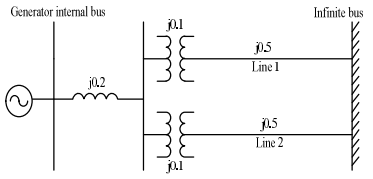
Q. The single line diagram of a balanced power system is shown in the figure. The voltage magnitude at the generator internal bus is constant and 1.0 p.u. The p.u. reactances of different components in the system are also shown in the figure. The infinite bus voltage magnitude is 1.0 p.u. A three-phase fault occurs in the middle of line 2. The ratio of the maximum real power that can be transferred during the pre-fault condition to the maximum real power that can be transferred under the faulted condition is

- 5
- 2.286
- 4.5
- 1.114
Q. The magnitude of three-phase fault currents at buses A and B of a power system are 10 pu and 8 pu, respectively. Neglect all resistances in the system and consider the pre-fault system to be unloaded. The pre-fault voltage at all buses in the system is 1.0 pu. The voltage magnitude at bus B during a three-phase fault at bus A is 0.8 pu. The voltage magnitude at bus A during a three-phase fault at bus B, in pu, is
- 0.28
- 0.47
- 0.65
- 0.84
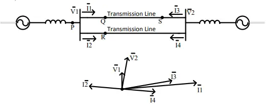
Q. A sustained three-phase fault occurs in the power system shown in the figure. The current and voltage phasors during the fault (on a common reference), after the natural transients have died down, are also shown. Where is the fault located?

- Location P
- Location Q
- Location R
- Location S
Q. Three-phase to ground fault takes place at locations F1 and F2 in the system shown in the figure.

If the fault takes place at location F1, then the voltage and the current at bus A are VF1 and IF1 respectively. If the fault takes place at location F2, then the voltage and the current at bus A are VF2 and IF2 respectively. The correct statement about voltages and currents during faults at F1 and F2, is
- VF1 leads IF1 and VF2 leads IF2
- VF1 leads IF1 and VF2 lags IF2
- VF1 lags IF1 and VF2 leads IF2
- VF1 lags IF1 and VF2 lags IF2
Q. A 3-phase generator rated at 110 MVA, 11 kV is connected through circuit breakers to a transformer. The generator is having direct axis sub-transient reactance Xd“= 19%, transient reactance Xd‘ =26% and synchronous reactance = 130%. The generator is operating at no load and rated voltage when a three-phase short circuit fault occurs between the breakers and the transformer. The magnitude of initial symmetrical RMS current in the breakers will be
- 22.20 kA
- 4.44 kA
- 38.45 KA
- 30.39 kA
Q. For the configuration shown in the figure the breaker connecting a large system to bus 2 is initially open. The system 3-phase fault level at bus 3 under this condition is not known. After closing the system breaker, the 3-phase fault level at bus 1 was found to be 5.0 p.u. What will be the new 3-phase fault level at system bus 3 after the interconnection? All per unit values are on a common base. Prefault load currents are neglected and pre-fault voltages are assumed to be 1.0 p.u. at all buses.

- 19.8 pu
- 15.64 pu
- 11.4285 pu
- 12 pu
Q. A 50 Hz alternator is rated 500 MVA, 20 kV, with Xd = 1.0 per unit and Xd” = 0.2 per unit. It supplies a purely resistive load of 400 MW at 20 kV. The load is connected directly across the generator terminals when a symmetrical fault occurs at the load terminals. The initial RMS current in the generator in per unit is
- 7.22
- 6.4
- 3.22
- 2.2
