Digital circuits can be divided into two types that are – combinational logic circuits and sequential logic circuits. Sequential logic circuits require a memory whereas combinational logic circuits do not require memory as its output depends only on the present inputs. Logic gates, adder, subtractor, multiplexer, demultiplexer, encoder, decoder, etc. are examples of combinational circuit components. Here, we have discussed the difference between encoder and decoder.
Difference between Encoder and Decoder in tabular form
In the following table, we have discussed the differences between encoder and decoder
| Encoder | Decoder |
| An encoder is a combinational circuit component that encodes a set of binary code into another set of binary code with a lesser number of bits. | A decoder is a combinational circuit component that decodes a set of binary codes into another set of binary codes with a greater number of bits. |
| The encoder has multiple input pins (m) and the number of input pins is given by the relation m ≤ 2n where n is the number of outputs. | The decoder has multiple inputs too but the number of inputs can be any positive number (n). |
| The encoder has multiple outputs but the number of outputs is always lesser than the number of inputs. | The decoder has multiple output lines and the number of output lines is given by the relation m ≤ 2n where n is the number of input lines. |
| The input-output pin ratio of an encoder is usually = 2n:n. | The input-output pin ratio of a decoder is usually = n:2n. |
| The purpose of using an encoder is to reduce the number of bits. | The purpose of using a decoder is to increase the number of bits for a specific reason. |
| Applications: Octal-to-binary converter, decimal-to-BCD converter, hexadecimal-to-binary converter, etc. are examples of the application of encoders |
Applications: Binary-to-octal converter, BCD-to-decimal converter, binary-to-hexadecimal converter, etc. are examples of the applications of decoders. |
What is an Encoder?
An encoder is a combinational circuit component that encodes a set of binary codes into another set of binary codes of a lesser number of bits. It is a very important and useful component that lets data transfer using a lesser number of bus lines.
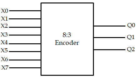
An encoder has multiple input and output pins. The number of input pins is given by the relation m ≤ 2n where n is the number of output pins. An encoder is expressed as 2n:n encoder i.e., 4:2 encoder, 8:3 encoder, 16:4 encoder, etc. though it is not always necessary because encoders like decimal to binary also exist which is expressed as a 10-to-4 encoder. It encodes decimal 0-9 into 4-bit BCD. Below we have given a block diagram of an 8:3 encoder:

Where, X0, X1, X2, X3, X4, X5, X6, X7 are the input lines.
And, Q0, Q1, Q2 are the outputs.
The input-output relationship of an 8:3 encoder can be explained using the following truth table:
|
INPUT |
OUTPUT |
|||||||||
|
X0 |
X1 |
X2 |
X3 |
X4 |
X5 |
X6 |
X7 |
Q2 |
Q1 |
Q0 |
|
1 |
0 |
0 |
0 |
0 |
0 |
0 |
0 |
0 |
0 |
0 |
|
0 |
1 |
0 |
0 |
0 |
0 |
0 |
0 |
0 |
0 |
1 |
|
0 |
0 |
1 |
0 |
0 |
0 |
0 |
0 |
0 |
1 |
0 |
|
0 |
0 |
0 |
1 |
0 |
0 |
0 |
0 |
0 |
1 |
1 |
|
0 |
0 |
0 |
0 |
1 |
0 |
0 |
0 |
1 |
0 |
0 |
|
0 |
0 |
0 |
0 |
0 |
1 |
0 |
0 |
1 |
0 |
1 |
|
0 |
0 |
0 |
0 |
0 |
0 |
1 |
0 |
1 |
1 |
0 |
|
0 |
0 |
0 |
0 |
0 |
0 |
0 |
1 |
1 |
1 |
1 |
An encoder is a very important component of digital electronics. Octal-to-Binary encoder, Decimal-to-Binary encoder, Hexadecimal-to-binary encoder are a few examples of encoders.
What is a Decoder?
A decoder is a combinational circuit component that decodes a particular binary code and accordingly gives another sequence of binary digits of a greater number of bits.
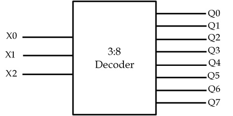
A decoder also has multiple inputs and output pins but, in this case, the number of output pins is greater than the number of input pins. The number of output pins is given by the relation m ≤ 2n where n is the number of input pins. A decoder is expressed as n:2n decoder such as 2:4 decoder, 3:8 decoder, 4:16 decoder, etc. Though it is not always necessary because decoders such as BCD to decimal decoder exist which is expressed as a 4-to-10 decoder. It decodes 4-bit binary numbers into decimal 0-9 where some combinations are repeated or skipped. We have given a block diagram of a 3:8 decoder:

Where, X0, X1, X2 are the input lines.
And, Q0, Q1, Q2, Q3, Q4, Q5, Q6, Q7 are the output lines.
The input-output relationship of a 3:8 decoder can be explained using the following truth table:
|
INPUT |
OUTPUT |
|||||||||
|
X0 |
X1 |
X2 |
Q0 |
Q1 |
Q2 |
Q3 |
Q4 |
Q5 |
Q6 |
Q7 |
|
0 |
0 |
0 |
1 |
0 |
0 |
0 |
0 |
0 |
0 |
0 |
|
0 |
0 |
1 |
0 |
1 |
0 |
0 |
0 |
0 |
0 |
0 |
|
0 |
1 |
0 |
0 |
0 |
1 |
0 |
0 |
0 |
0 |
0 |
|
0 |
1 |
1 |
0 |
0 |
0 |
1 |
0 |
0 |
0 |
0 |
|
1 |
0 |
0 |
0 |
0 |
0 |
0 |
1 |
0 |
0 |
0 |
|
1 |
0 |
1 |
0 |
0 |
0 |
0 |
0 |
1 |
0 |
0 |
|
1 |
1 |
0 |
0 |
0 |
0 |
0 |
0 |
0 |
1 |
0 |
|
1 |
1 |
1 |
0 |
0 |
0 |
0 |
0 |
0 |
0 |
1 |
Decoders are a very important component of digital electronics. They are used to covert Binary-to-Octal, Binary-to-Decimal, Binary-to-Hexadecimal, etc.
Conclusion
Encoders and decoders are compliments of each other. One’s input to output conversion can be reversed by another. That is why in some circuits, encoders are used in the transmitter section to reduce the number of bits transmitted and decoders are used in the receiver section to decode the received signal. There are also many other applications of encoders and decoders.
Author
Subhrajyoti Choudhury
