A DAC (Digital-to-Analog Converter) is used to convert a digital signal to the analog format.
An example of DAC: music stored in a DVD in digital format must be converted to an analog voltage for playing out on a speaker.
Consider a DAC system having N-bit digital input and an analog output. The block diagram is shown below.
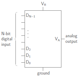
For a 3-bit DAC, with input S2S1S0, the output voltage is given by
VA = K[(S2 × 22) + (S1 × 21) + (S0 × 20)]
In general, DAC output voltage is given by

where, K is proportional to the reference voltage VR.
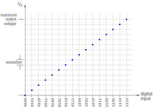
The graph between the output voltage and digital input is given below.
1. DAC using binary-weighted resistors
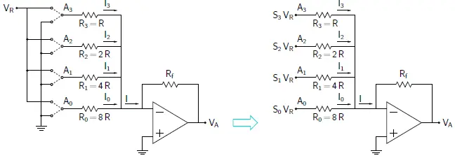
Consider the DAC as shown in above figure. It is a 4 bit DAC.
If the input bit Sk is 1, Ak gets connected to reference voltage VR; else, it gets connected to ground.
V(Ak) = Sk × VR .
Since the inverting terminal of the Op Amp is at virtual ground,

Using,

We get,

The output voltage is given by

Drawback of DAC using binary-weighted resistors
The output voltage variation can be reduced by using resistors with a smaller tolerance.
However, it is difficult to fabricate an IC with widely varying resistance values (from R to 2N−1R) and each with a small enough tolerance.
2. R-2R ladder network DAC
The R-2R ladder network circuit is shown below. A0 is the least significant bit and A3 is the most significant bit. Node Ak (k=0,1,2,3….) is connected to reference voltage VR if input bit Sk is 1; else, it is connected to ground.
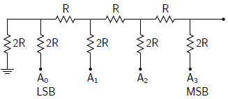
Its equivalent circuit is given as
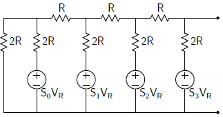
To find the analog output voltage, we have to drive the Thevenin equivalent circuit for this network. For Thevenin circuit, first, we calculate the Thevenin’s equivalent resistance. After that Thevenin voltage corresponding to each Sk = 1. (where, k=0,1,2,3)
Thevenin resistance
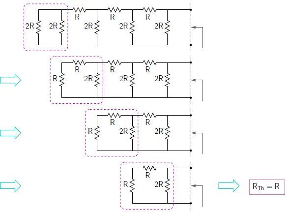
Therefore, Thevenin’s resistance is given by, RTh = R
VTh for input S0 =1
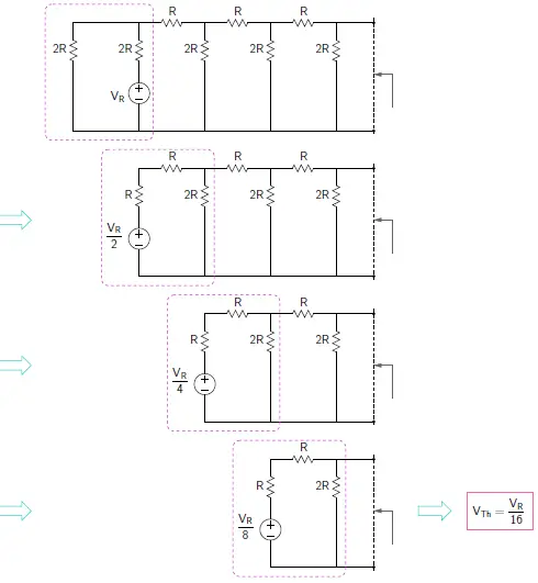
Therefore, Thevenin voltage for S0 = 1 is VTh (S0) = VR/16
VTh for input S1 =1
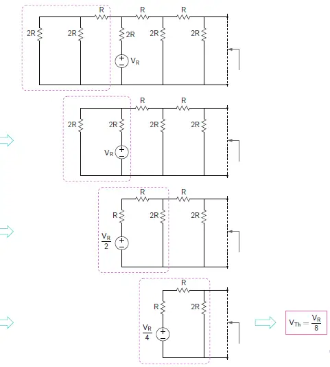
Therefore, Thevenin voltage for S1 = 1 is VTh (S1) = VR/8
VTh for input S2 =1
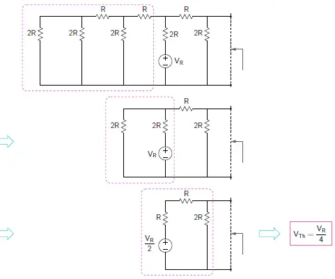
Therefore, Thevenin voltage for S2 = 1 is VTh (S2) = VR/4
VTh for input S3 =1
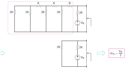
Therefore, Thevenin voltage for S3 = 1 is VTh (S3) = VR/2
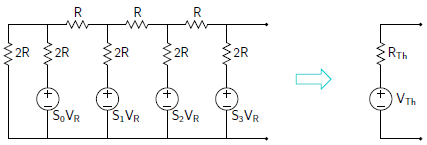
VTh = VTh (S0) + VTh (S1) + VTh (S2) + VTh (S3)

So by connecting the R-2R ladder to an Op Amp, forms a DAC as shown below.

The DAC output voltage is given by

The above circuit is for 4 bit DAC. For N bit DAC, the output voltage is given by

