Sigma-delta Analog-to-Digital Converter (ADC) is used in many application including telecommunications for analog to digital conversion.
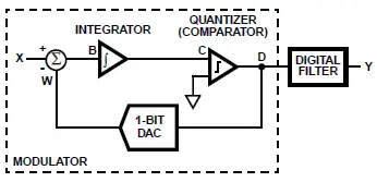
A Sigma-delta ADC has a modulator and a digital filter (also called as decimation filter) as shown in Fig. 1. A modulator converts the input analog signal into digital bit streams (1s and 0s).

The Sigma-delta ADC method is based on delta modulation where the difference between two successive samples (increase or decrease) is quantized.
Working of Sigma-delta ADC
The Sigma-delta ADC consists of two parts i.e. modulator & digital filter. The modulator circuit consists of an integrator, comparator and 1 bit DAC (Digital to Analog converter). The working of a modulator can be explained using a conversion example.
In Table, the Alphabets X, B, C, D, and W correspond to points in the signal path of the block diagram in Fig1. Suppose the input X is a DC input of 3/8 V. The resultant signal voltage at each point in the signal path for each signal sample is shown in the Table.
B = A − Wn-1 (previous value of W)
C = B + Cn-1 (previous value of C)
D = 0 (if C is negative)
= 1 (if C is o or positive)
W = +1 (if D is 1)
= −1 (if D is o)
| Sample Number (n) | X | B | C | D | W |
| 0 | 3/8 | 0 | 0 | 0 | 0 |
| 1 | 3/8 | 3/8 | 3/8 | 1 | +1 |
| 2 | 3/8 | -5/8 | -2/8 | 0 | -1 |
| 3 | 3/8 | 11/8 | 9/8 | 1 | +1 |
| 4 | 3/8 | -5/8 | 4/8 | 1 | +1 |
| 5 | 3/8 | -5/8 | -1/8 | 0 | -1 |
| 6 | 3/8 | 11/8 | 10/8 | 1 | +1 |
| 7 | 3/8 | -5/8 | 5/8 | 1 | +1 |
| 8 | 3/8 | -5/8 | 0/8 | 0 | -1 |
| 9 | 3/8 | 11/8 | 11/8 | 1 | +1 |
| 10 | 3/8 | -5/8 | 6/8 | 1 | +1 |
| 11 | 3/8 | -5/8 | 1/8 | 1 | +1 |
| 12 | 3/8 | -5/8 | -4/8 | 0 | -1 |
| 13 | 3/8 | 11/8 | 7/8 | 1 | +1 |
| 14 | 3/8 | -5/8 | 2/8 | 1 | +1 |
| 15 | 3/8 | -5/8 | -3/8 | 0 | -1 |
| 16 | 3/8 | 11/8 | 8/8 | 1 | +1 |
| 17 | 3/8 | -5/8 | 3/8 | 1 | +1 |
| 18 | 3/8 | -5/8 | -2/8 | 0 | -1 |
Note: A repetitive pattern develops every sixteen samples and that the average of the signal W over samples 1 to 16 is 3/8. It shows that the feedback loop forces the average of the feedback signal W to be equals to the input X.
Summary
- Delta modulation is a 1-bit quantization method.
- The output of a delta modulator (D) is a single-bit data stream where the relative number of 1s and 0s indicate the level or amplitude of the input signal.
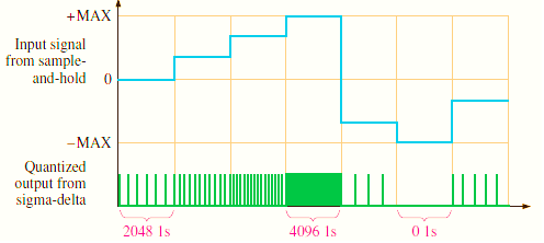
- The fig2. shows the Sigma-delta ADC conversion.
- The number of 1s over a given number of clock cycles establishes the signal amplitude during that interval.
- A maximum number of 1s corresponds to the maximum positive input voltage. 4096 1s occurs when the input is positive maximum.
- A number of 1s equal to one-half the maximum corresponds to an input voltage of zero. 2048 1s occurs when the input is zero.
- No 1s (all 0s) corresponds to the maximum negative input voltage. 0 1s occur when the input is negative maximum.

