In this article, we will learn about Sample and Hold (S/H) Circuit. These circuits are used in Analog to Digital (ADC) conversion and Switched Capacitor filters. Sample and hold circuits are used to sample an analog signal and to store its value for some length of time (for digital code conversion).
Function of Sample & Hold (S/H) Circuit
The function of the Sample & Hold Circuit is to sample an analog input signal and hold this value over a certain length of time for subsequent processing. The sampling period may be from 1 to 10 µS. The holding period may be from a few milliseconds to several seconds.
- It is heavily used in data converters.
- They are also referred to as track-and-hold circuits.
Working of Sample & Hold Circuit
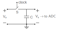
The simplest circuit diagram of (S/H) Circuit is shown below.

Va = input signal
S = MOS transistor operating as the sampling switch
C = hold capacitor
Vs = resulting sample & hold output signal
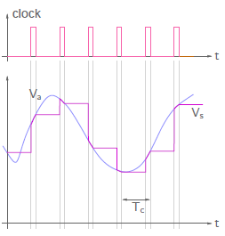
The Switch is operated by a clock pulse. The clock pulse controls whether to sample the input signal or hold the last sampled value of the input signal. When the Clock pulse is high, the input signal Va is sampled and when the clock pulse is low, Va value is held. Thus the circuit has two modes of operation depending upon the logic level of sample & hold clock signal. The Switch clock pulse and circuit output are shown in the figure below.

Upon receiving the clock pulse, the switch S is closed and the circuit samples the input. This mode of operation is called as SAMPLE mode. The output voltage Vs follows input i.e. output tracks the input so called TRACK mode of operation. After clock pulse is removed, the switch S is open and the circuit holds the output at a value which input signal had at an instant of pulse deactivation. This mode of operation is called as HOLD mode.
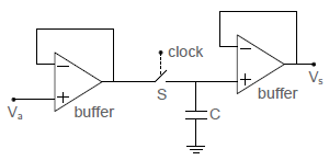
The following figure shows a typical sample & hold circuit using op-amps.

Op Amp buffers are used to minimise loading effects.
Applications
1. Used in Analog to Digital Converters (ADC)
Out of different ADCs, successive approximation type ADC uses S/H circuit.
2. Used in Digital to Analog Converters.
3. Used in analog demultiplexing in data distribution and in analog delay lines.
