In combinational circuits, we deal with the devices whose output depends solely on the present inputs and not on the past inputs. Logic gates, encoder, decoder, multiplexer, demultiplexer are examples of such combinational logic circuit elements. Here we are going to discuss Encoder and Multiplexer. They have a few things in common such as, both of them are used to minimize the output, both have 2n number of input pins, etc. But in this article, we are going to discuss the difference between encoder and multiplexer.
Difference between Encoder and Multiplexer in tabular form
In the following table, we have pointed out some differences between encoder and multiplexer.
| Encoder | Multiplexer |
| The encoder is a combinational circuit element that encodes a set of binary codes into another set of binary codes containing a smaller number of bits. | The multiplexer is a combinational circuit element that channels one of its many inputs to its only output depending on the selection inputs. |
| An encoder has n number of outputs if it has 2n number of input pins. | A multiplexer has only one output pin irrespective of the number of input pins. |
| If an encoder has 2n number of input pins then it will have n number of output pins. | A multiplexer has multiple numbers of input pins and the number of input pins is given by 2n and it has only 1 output. |
| The encoder does not have any selection input lines. | If a multiplexer has 2n number of input pins then it will have n number of selection lines. |
| The encoder is used to encode a particular set of binary sequences into another set binary sequence of a smaller number of bits. | The multiplexer is used to multiplex one of its input signals into its output depending on the selection input. |
| 8-bit code to BCD, 16-bit code to 4-bit binary code, etc. are the examples of applications of the encoder. | Parallel to serial converter, digital switch, signal multiplexing, etc. are the examples of applications of the multiplexer. |
What is an Encoder?
An encoder is a combinational logic device that is used to encode a binary number sequence into another binary number sequence of a smaller number of bits.
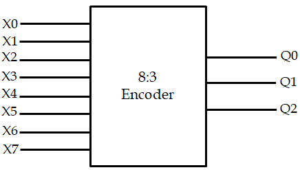
An encoder can have 2n number of input lines where n is the number of output lines. It encodes a binary code of 2n number of bits into n number of bits. Unlike multiplexers, the encoder does not have selection lines. An encoder is expressed as 2n:n encoder i.e., 4:2 encoder, 8:3 encoder, 16:4 encoder, etc. The block diagram of an 8:3 encoder is given below:

Where, X0, X1, X2, X3, X4, X5, X6, X7 denote the input lines.
And, Q0, Q1, Q2 denote the outputs.
The truth table of this encoder is given below:
|
INPUT |
OUTPUT |
|||||||||
|
X0 |
X1 |
X2 |
X3 |
X4 |
X5 |
X6 |
X7 |
Q0 |
Q1 |
Q2 |
|
1 |
0 |
0 |
0 |
0 |
0 |
0 |
0 |
0 |
0 |
0 |
|
0 |
1 |
0 |
0 |
0 |
0 |
0 |
0 |
0 |
0 |
1 |
|
0 |
0 |
1 |
0 |
0 |
0 |
0 |
0 |
0 |
1 |
0 |
|
0 |
0 |
0 |
1 |
0 |
0 |
0 |
0 |
0 |
1 |
1 |
|
0 |
0 |
0 |
0 |
1 |
0 |
0 |
0 |
1 |
0 |
0 |
|
0 |
0 |
0 |
0 |
0 |
1 |
0 |
0 |
1 |
0 |
1 |
|
0 |
0 |
0 |
0 |
0 |
0 |
1 |
0 |
1 |
1 |
0 |
|
0 |
0 |
0 |
0 |
0 |
0 |
0 |
1 |
1 |
1 |
1 |
The encoder is a very important device in combinational circuits. It is used to reduce the number of bits for a particular set of binary codes.
What is a Multiplexer?
A multiplexer is nothing but a digital switch that switches its output value from one input to another depending on the selection inputs. A multiplexer has multiple input lines and only one output line. It is a combinational logic device that changes the output value from one input value to another depending on the selection line inputs.
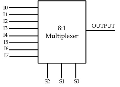
The number of input pins of a multiplexer is given by 2n where n is the number of selection lines i.e., for 3 selection lines, a multiplexer will have 23 = 8 number of input pins. A multiplexer is also called a MUX and it is denoted by 2n:1 MUX i.e., 2:1 multiplexer, 4:1 multiplexer, 8: 1 multiplexer, 16:1 multiplexer, etc. Here, 2n stands for the number of inputs, n is the number of selection lines and ‘1’ stands for the number of outputs. Below we have given a block diagram of an 8:1 multiplexer:

Where, I0, I1, I2, I3, I4, I5, I6, I7 denote the input lines.
And, S0, S1, S2 denote the selection inputs.
The output of an 8:1 multiplexer is dependent on its 3 selection line inputs and can be expressed by following truth table:
| S2 | S1 | SO | Output (F) |
| 0 | 0 | 0 | I0 |
| 0 | 0 | 1 | I1 |
| 0 | 1 | 0 | I2 |
| 0 | 1 | 1 | I3 |
| 1 | 0 | 0 | I4 |
| 1 | 0 | 1 | I5 |
| 1 | 1 | 0 | I6 |
| 1 | 1 | 1 | I7 |
Where, S2, S1, S0 are the selection inputs,
And, I0, I1, I2, I3, I4, I5, I6, I7 are the input lines.
The multiplexer is one of the most popular and one of the most used combination circuit elements. It acts as a digital switch. Parallel to serial converter, multiplexing signals in TDM, etc. are examples of its applications.
Conclusion
Encoder and multiplexer have their similarities and differences. Both of them have 2n number of inputs, both of them are used to reduce the number of output bits, etc. But their purposes are different. Encoder and multiplexer, both are very important components of combinational circuits.
Author
Subhrajyoti Choudhury
